Description
In electronics projects, creating an interface between user and system is very important. This interface could be created by displaying useful data, a menu, and ease of access. A beautiful design is also very important. There are several components to achieve this like TFT Displays. For more information Click Here.
Stone Technologies is a professional Manufacturer of HMI Intelligent TFT LCD modules. Depending on the application the Stone Technologies offers Industrial Type, Advanced type, and Civil Type Intelligent TFT LCD modules available in different sizes. Visit Here.
GUI And Description
The HMI intelligent TFT LCD Module is provided with all the necessary documents explaining the basic connection, Development Software, GUI individual Design, and operation. But for further description and knowledge please find the below explanation and ( Note :- the details of the products used in the project is given in the procedure). The product manual gives you an overview of the Communication and Operation, Basic functions, working principle, GUI Design Software, Information about the Industrial type, Advanced Type, and Civil Type HMI TFT LCD Modules
Firstly for the design download the GUI software provided in the link given below. Then further proceeding step would be to click on “file->New” the same can be seen in the video itself. Now further select the screen size would be 800 X 480 for a 5 inch display. After both the steps have been completed then select and add the image and icon of GUI design for the display. The same can be found in the below article. Refer the below video to follow the step by step procedure for any difficulty in the procedure. Add a button so that you can switch from screen “1” to screen “2” and vice-versa PS- (Refer video for ambiguity in the procedure). Further add address and address key for every color in the variable property section. Similarly repeat the procedure for every button and every color. Finally click on upload button to publish the output. For more reference please view the video below.
Product Description (Used in this project).

► Size: 5″
► CPU: Cortex M4
► Resolution: 800×480 (16:9)
► Interface: RS232/RS485/TTL/USB
► Viewing Area (mm): 108.0*64.8
►Brightness(cd/m²): 400; 350; 400
Circuit Diagram

Working
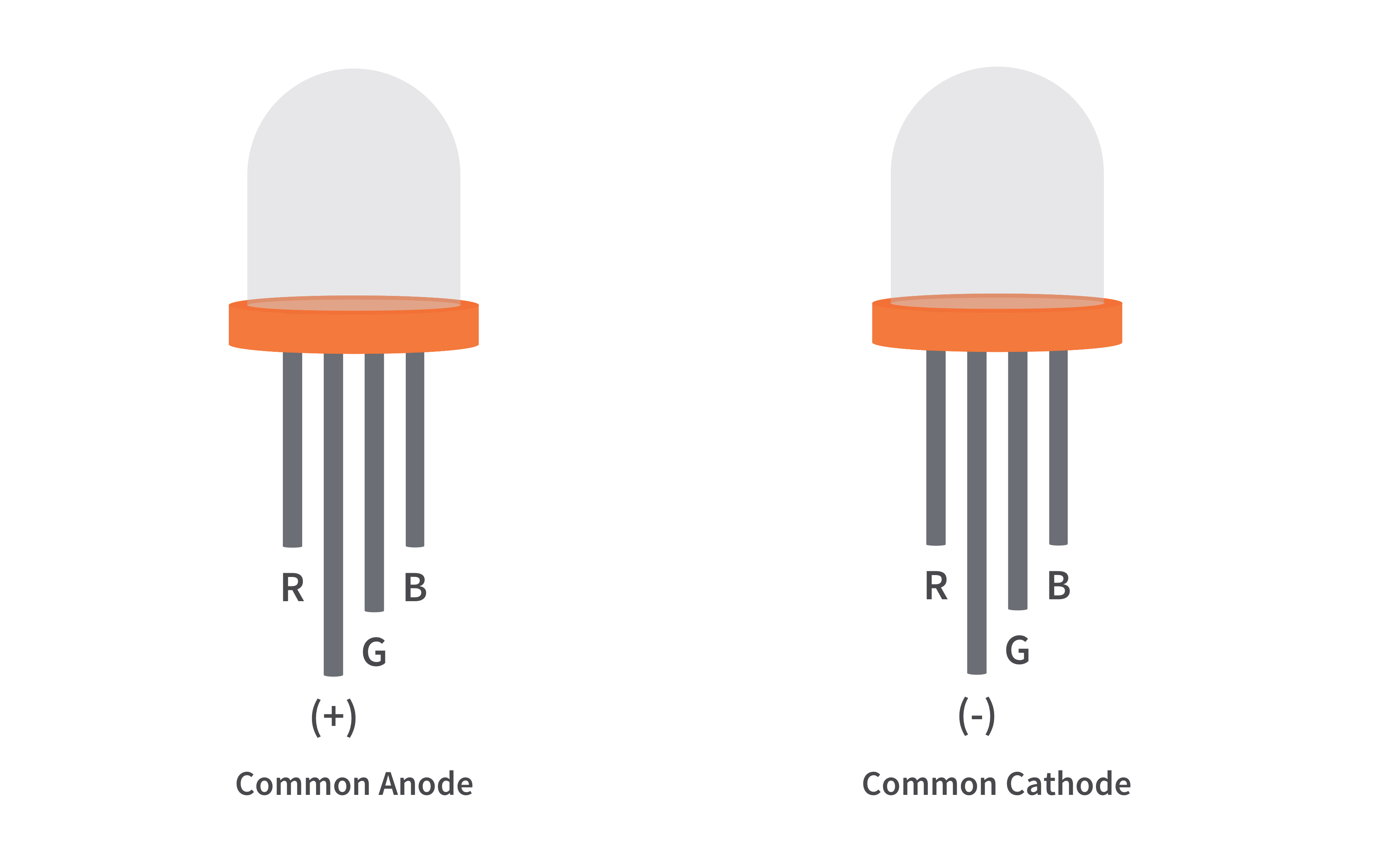
RGB LED is a type LED which emit multiple colors i.e. Red, Green and Blue to be specific. Hence, it is called RGB LED (RGB stands for Red, Green and Blue). Appearance wise, an RGB LED looks very similar to a regular LED except that an RGB LED has three LEDs, each for Red, Green and Blue lights and all these are housed in a single package.

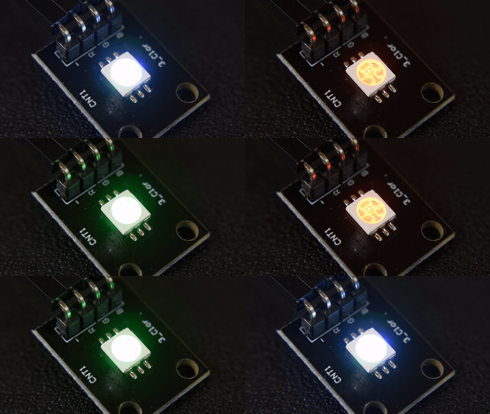
Using an RGB LED, you can ideally generate any color by controlling the brightness of the individual Red, Green and Blue LEDs. The following image shows a few possible colors of light that can be generated using an RGB LED.

You might have performed an experiment with dimming an LED using Arduino, where the brightness of LED is controlled either directly using the program or by interfacing a potentiometer. The technique used to control the brightness of an LED is called Pulse Width Modulation or simply PWM.
PWM is a technique where the amount of power delivered to a device can be controlled accurately and efficiently. PWM technique can be used to control the brightness of an LED, the speed of a motor or the direction of a servo motor.
There are two important factors to consider when dealing with PWM Technique: Duty Cycle and Frequency. Duty cycle indicates the duration for which the pulse is HIGH over it period. It is measured in percentage and it indicates the voltage between OFF and ON levels (usually 0V and 5V). Arduino UNO has 6 Pins that can be used to generate PWM Signals: 3, 5, 6, 9, 10 and 11. In order to generate PWM signal of a specific duty cycle, you need to use the analogWrite(pin, value); function. Here, the value varies from 0 – 255 and corresponds to 0 – 100% Duty cycle.
First, an important point is that, since we will be using the PWM technique to control the brightness of the LEDs (Red, Green and Blue separately), make sure that you connect the Red, Green and Blue Anodes of the RGB LED to three PWM supported pins of Arduino (assuming you have a common cathode RGB LED). The interfacing with the TFT display can be seen in the circuit Diagram
For more reference like circuit diagram, Videos and Output Click Here.

Arduino Code
//For more information about this project visit:- wwww.electrocircuit.net //
#include <SoftwareSerial.h>
SoftwareSerial max232(2,3);
char data;
String mystring;
int R = 9;
int G = 10;
int B = 11;
void setup()
{
Serial.begin(115200);
max232.begin(115200);

pinMode(R, OUTPUT);      /////////RED////////
digitalWrite(R, LOW);

pinMode(G, OUTPUT);      ////////GREEN///////
digitalWrite(G, LOW);

pinMode(B, OUTPUT);     ///////BLUE/////////
digitalWrite(B, LOW);
}
void loop()
{
if (max232.available()>0)
 {
   data = max232.read();
   mystring = mystring + byte(data) ;
   delay(10);
 }

if (mystring.endsWith("101"))
  {
    mystring = "";
   digitalWrite(R,HIGH);
   digitalWrite(G,LOW);
   digitalWrite(B,LOW);
  }
if (mystring.endsWith("102"))
  {
   mystring = "";
   digitalWrite(G,HIGH);
   digitalWrite(R,LOW);
   digitalWrite(B,LOW);
  }
if (mystring.endsWith("103"))
  {
  mystring = "";
  digitalWrite(B,HIGH);
  digitalWrite(G,LOW);
  digitalWrite(R,LOW);
  }
if (mystring.endsWith("104"))
  {
   mystring = "";
   digitalWrite(B,HIGH);
   digitalWrite(R,HIGH);
   digitalWrite(G,LOW);
  }
if (mystring.endsWith("105"))
  {
   mystring = "";
   digitalWrite(G,HIGH);
   digitalWrite(R,HIGH);
   digitalWrite(B,LOW);
  }
if (mystring.endsWith("106"))
  {
   mystring = "";
   digitalWrite(B,HIGH);
   digitalWrite(G,HIGH);
   digitalWrite(R,LOW);
  }
if (mystring.endsWith("107"))
  {
  mystring = "";
  digitalWrite(G,HIGH);
  digitalWrite(B,HIGH);
  digitalWrite(R,HIGH);
  }
}

