

List of Components
- Arduino UNO
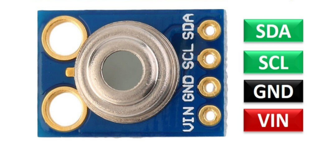
- MLX90614 Sensor
- Tuya Communication Board
- Few Jumper Wires
How temperature Sensor works?
In this project we are using MLX90614 Sensor, the key feature of MLX90614 is that it is a contactless IR temperature sensor with high accuracy. So it can be used in industries to measure the temperature of moving objects also. Due to its high accuracy and precision, it is also used in a wide range of commercial, health care, and household applications like room temperature monitoring, body temperature measurement, etc.
Working Principle of MLX90614
It works on the Stefan-Boltzmann Law which state that all object and living being emit energy in the form of IR waves and this IR intensity directly proportional to the temperature of that body ,that means if any object emits high IR energy then it will has high temperature also. And this sensor gives the two temperature one is object and another one is ambient temperature and this data of temperature transfer through I2C protocol ,so that why it has two communication wires SDA [Serial Data] and SCL [Serial Clock] .
This sensor does not required any other external components to connect with it ,you can connect it with Arduino because Arduino has 5volt supply and also has I2C protocol. So let’s start with this project.
GUI Designing and Implementation with Tuya
Let’s start first with interface design, for this first go to this Tuya IoT platform link Click Here.
https://auth.tuya.com/?_source=293d65b4984ba4f9ba91ac4ef491a6ab
Note:- If you do not have account on this platform use sign-up button to create new one, then go further.
After login you will get this type of interface which is a IoT platform to develop and make new projects.

Now click on Create button to make a new project and select these options as shown in the below image, that is first select ‘Socket’ then from that select ‘custom function’ and in that click on ‘Plug’ option and after clicked you will get a new page where you have to fill information about new project like which type of communication you are using in this and name of the project.

Now fill all the information as per given in below image like name and protocol, after this click on create button.

After this you will get this screen where select ‘Custom Function’ and from that click on ‘Add’ button to add the DPID for object temperature and Ambient temperature ,for DPID you have select some parameter like which type of data you want to send or receive as we know temperature data is going to in the form of some value range.

As you can see in the image there are two DPIDs and these DPIDs have some parameter and here we have selected data transfer type as report only because we are receiving the data from sensor so it is going to be report that data to the Tuya cloud. And this sensor has temperature range -70 to 380 degrees so we have selected this range , here are the two DPID and these has individual DP values ,object DP has 101 and Ambient has 102 and these value are important for the coding part because we are going to send the data with the help these IDs values, so remember these value for coding purpose.

After done with above part let’s build the interface for the Tuya application, and this editor look like this as you can see in the below image. For this you have to click on ‘Device Panel’ part after done with above part and then click on ‘Blank panel’ then you will redirect to this page with new tab.
There are many option to create a interface according to your choice only you have to drag that feature whatever you want to add in this area where ‘Drag Component’ is written. So here first we will add our background image which we have created for this project ,you can find this image by click here


This image has two things first is Object temperature and another one is Ambient temperature .if you want to use this image just click on this and download it ,you can use your own image also.
Let’s use this image in this , in the left there are two options for DPIDs which we have created now firs select ‘Dp Object’ option and you will get different -different option for reading interface as you can see in the image. Then drag it whatever you want and do this ting for ‘Dp Ambient; also ,after selecting choose color and don’t forget to put both reading front , and things you can do it by right click on that particular reading.

Here we have added graph also for both reading value versus sum of value and you can set it by day ,hour or month ,for this go to graph section and drag it from there and put it in editing area and don’t forget to add the attribute for both graph otherwise you will get blank graph at the time of simulation.
After this we have completed the designing part now it is the time of testing ,to do this you have to save your design and release it, so release it ,and at this time you will get option for testing as you can see in below image use your QR code and scan it with your phone which have Tuya Smart app and test the design part. Let’s move further to implement the coding part for this you need Arduino software and Tuya communication board, so let jump to that part.

Arduino Coding
Code
#include <TuyaWifi.h>
#include <SoftwareSerial.h>

#include <Wire.h>
#include <Adafruit_MLX90614.h>
Adafruit_MLX90614 mlx = Adafruit_MLX90614();

TuyaWifi my_device;
SoftwareSerial DebugSerial(8,9);

/* Current LED status */
unsigned char led_state = 0;
/* Connect network button pin */
int wifi_key_pin = 7;

/* Data point define */
#define ObjectTemp  101
#define AmbientTemp  102

/* Current device DP values */

long x= 0;
long y= 0;

/* Stores all DPs and their types. PS: array[][0]:dpid, array[][1]:dp type.
 *                                     dp type(TuyaDefs.h) : DP_TYPE_RAW, DP_TYPE_BOOL, DP_TYPE_VALUE, DP_TYPE_STRING, DP_TYPE_ENUM, DP_TYPE_BITMAP
*/
unsigned char dp_array[][2] = {

    {ObjectTemp , DP_TYPE_VALUE},
    {AmbientTemp, DP_TYPE_VALUE},
};

unsigned char pid[] = {"7y4c8gqh8xw3c8bf"};
unsigned char mcu_ver[] = {"1.0.0"};

/* last time */
unsigned long last_time = 0;

void setup()

{
    mlx.begin();
    Serial.begin(9600);
    DebugSerial.begin(9600);
    //Initialize led port, turn off led.
    pinMode(LED_BUILTIN, OUTPUT);
    digitalWrite(LED_BUILTIN, LOW);
    //Initialize networking keys.
    pinMode(wifi_key_pin, INPUT_PULLUP);
    //Enter the PID and MCU software version
    my_device.init(pid, mcu_ver);
    //incoming all DPs and their types array, DP numbers
    my_device.set_dp_cmd_total(dp_array, 2);
   //register DP download processing callback function
    my_device.dp_process_func_register(dp_process);
    //register upload all DP callback function
    my_device.dp_update_all_func_register(dp_update_all);

    last_time = millis();
}

void loop()
{
    my_device.uart_service();
    //Enter the connection network mode when Pin7 is pressed.
    if (digitalRead(wifi_key_pin) == LOW) {
        delay(80);
        if (digitalRead(wifi_key_pin) == LOW) {
            my_device.mcu_set_wifi_mode(SMART_CONFIG);
        }
    }
  /* LED blinks when network is being connected */
    if ((my_device.mcu_get_wifi_work_state() != WIFI_LOW_POWER) && (my_device.mcu_get_wifi_work_state() != WIFI_CONN_CLOUD) && (my_device.mcu_get_wifi_work_state() != WIFI_SATE_UNKNOW)) {
        if (millis() - last_time >= 500) {
            last_time = millis();
            /* Toggle current LED status */
            if (led_state == LOW) {
                led_state = HIGH;
            } else {
                led_state = LOW;
            }

            digitalWrite(LED_BUILTIN, led_state);
        }
    }

  if ((my_device.mcu_get_wifi_work_state() == WIFI_CONNECTED) || (my_device.mcu_get_wifi_work_state() == WIFI_CONN_CLOUD))
   {
    x=mlx.readObjectTempC();
    y=mlx.readAmbientTempC();
    my_device.mcu_dp_update(ObjectTemp, x, 1);
    my_device.mcu_dp_update(AmbientTemp, y, 1);
   }
    delay(10);
}
unsigned char dp_process(unsigned char dpid,const unsigned char value[], unsigned short length)
{
  /* all DP only report */
  return SUCCESS;
}
void dp_update_all(void)
{
   my_device.mcu_dp_update(ObjectTemp, x, 1);
   my_device.mcu_dp_update(AmbientTemp, y, 1);
}
Above given code is for Arduino as you can see we have divided this code into three parts first is void setup function in this part all initialization is done for MLX-sensor and serial and its baud rate, and there are also function calling which present in Arduino and every function call is done in the setup function only. After this function there is void loop function which is using to connect with Wi-Fi because it will continuously run again and again and for the Wi-Fi triggering we are using pin number-7 of Arduino. this pin is required for the first time when we will add any new device/product with Tuya Smart app. For initialization this pin-7 should be connect with ground pin for up to 5 sec after after this remove that wire and then a new device will be pop-up in Tuya application for this you have to jus refresh it.
Then there is important function which is a dp_update_all this function is using for to update the sensor value separately .
  if ((my_device.mcu_get_wifi_work_state() == WIFI_CONNECTED) || (my_device.mcu_get_wifi_work_state() == WIFI_CONN_CLOUD))
   {
    x=mlx.readObjectTempC();
    y=mlx.readAmbientTempC();
    my_device.mcu_dp_update(ObjectTemp, x, 1);
    my_device.mcu_dp_update(AmbientTemp, y, 1);
   }
And this above code part helping us to get the sensor on time value ,as you can see the there is if condition ,it will go inside if there is Wi-Fi or device is connected with Wi-Fi. After that it will check the sensor value and store it in x for object value and for Ambient value in y, and update part will upload this data to Tuya cloud and it will reflect in your mobile application. So in this way code is working let move towards the output part ,so now upload this whole code and do the same procedure as said above.
After done with uploading part do the connection as per circuit-diagram given below. Do this connection after connected Tuya Wi-Fi board with Arduino.

Output Video
And thankyou so much to read the article till now there is YouTube video on this project so please go through that video to understand the whole procedure in a better manner there is link for video go and check it out.
YouTube video
