

Description
In electronics projects, creating an interface between user and system is very important. This interface could be created by displaying useful data, a menu, and ease of access. A beautiful design is also very important. There are several components to achieve this like TFT Displays. For more information Click Here.
Stone Technologies is a professional Manufacturer of HMI Intelligent TFT LCD modules. Depending on the application the Stone Technologies offers Industrial Type, Advanced type, and Civil Type Intelligent TFT LCD modules available in different sizes. Visit Here
Below are the steps you can use to develop the GUI :-
Step 1 and 2:
1.Step 1 shows the main screen where the color detection can be implemented
2.In Step 2 the page switch option can be used to switch between “0”image to “1” image.

Step 3 and 4:-
3. Step three shows how to select the animation icon for your animation, like in this case red, blue and Green color can be selected for the color detection process
4. In step 4 you have to select the memory address as per the code or the GUI/project you want to build, In this project the address is “0096”

Step 5:-
5. You can select the icon generator option as shown in the diagram and generate the red, blue, green icons or else please find below the project attachments for the icons

Step 6:-
6. Step 6 shows the animated values and the stop values for the respective colors red, blue and green

Circuit Diagram

Working
A color sensor detects the color of the material. This sensor usually detects color in RBG scale. This sensor can categorize the color as red, blue or green. These sensors are also equipped with filters to reject the unwanted IR light and UV light
To detect the color of material three main types of equipment are required. A light source to illuminate the material surface, a surface whose color has to be detected and the receivers which can measure the reflected wavelengths.
Colour sensors contain a white light emitter to illuminate the surface. Three filters with wavelength sensitivities at 580nm, 540nm, 450nm to measure the wavelengths of red, green and blue colors respectively.
Based on the activation of these filters, the color of the material is categorized. A light to voltage converter is also present in the sensor. The sensor responds to color by generating a voltage proportional to the detected color.
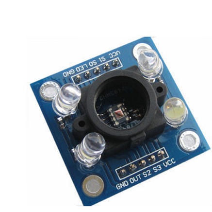
In this project we are going to interface color sensor with Arduino UNO. Color sensor which can detect any number of colors with right programming. TCS3200 contains RGB (Red Green Blue) arrays. As shown in figure on microscopic level one can see the square boxes inside the eye on sensor. These square boxes are arrays of RGB matrix. Each of these boxes contain Three sensors, One is for sensing RED light intensity, One is for sensing GREEN light intensity and the last in for sensing BLUE light intensity.
Although different colors have different sensitivity, for a normal use it won’t make much difference.
The UNO here send signal to module to detect colors and the data received by the module is shown in the TFT Display connected to it Click Here.
The UNO detects three color intensities separately and shows them on TFT display. The Uno can detect the signal pulse duration by which we can get the frequency of square wave sent by module. With the frequency at hand we can match it with color on sensor. As by above condition the UNO reads pulse duration on 10th pin of UNO and stores it value in “frequency” integer.
We are going to do this for all three colors for color recognition. All three color intensities are shown by frequencies on TFT Display. For the product used in the project Click Here.
For more information about the project like code, video and description Click Here.
Code
#define S0 4
#define S1 5
#define S2 6
#define S3 7
#define sensorOut 8
int r = 0;
int g = 0;
int b = 0;

#include <SoftwareSerial.h>
SoftwareSerial screenserial(2, 3); // RX, TX

#define ta 0x96
unsigned char ta_send[8]= {0xA5, 0x5A, 0x05, 0x82, 0x00, ta, 0x00, 0x00};
int x=0;
int y=0;
void setup()
{
  pinMode(S0, OUTPUT);
  pinMode(S1, OUTPUT);
  pinMode(S2, OUTPUT);
  pinMode(S3, OUTPUT);
  pinMode(sensorOut, INPUT);
  digitalWrite(S0,HIGH);
  digitalWrite(S1,LOW);
  Serial.begin(115200);
  screenserial.begin(115200);
}
void loop()
{
  digitalWrite(S2,LOW);
  digitalWrite(S3,LOW);
  r = pulseIn(sensorOut, LOW);
  Serial.print("R = ");
  Serial.print(r);

//////////////////////////////////////////////////////
  digitalWrite(S2,HIGH);
  digitalWrite(S3,HIGH);
  g = pulseIn(sensorOut, LOW);
  Serial.print(" G = ");
  Serial.print(g);

//////////////////////////////////////////////////////
  digitalWrite(S2,LOW);
  digitalWrite(S3,HIGH);
  b = pulseIn(sensorOut, LOW);
  Serial.print(" B = ");
  Serial.println(b);
if (b<140)
 {
  y=500;
 }
 else if(r<150)
 {
  y=300;
 }
 else if(g<200)
 {
  y=700;
 }

  ta_send[6]=y/256;
  ta_send[7]=y%256;
  screenserial.write(ta_send,8);
  delay(100);

}
For more information on Stone Technologies and this project Click here.