

Description
Dwin-HMI specialized in making High quality and cost effective HMI touch screens display.
In this tutorial I am going to make project based on Dwin-HMI TFT display, Here in this project you will find the Raspberry-Pi communicating with TFT display DWIN.
This DMG80480C043_02WTC has resolution of 480X800 and can be easily used with 5V compatible controller boards like Arduino Uno, Arduino Nano, Arduino Mega, PIC microcontrollers, 8051 family of microcontrollers, etc.
Tool Installation
For tool installation, I already explained in the first tutorial of Dwin you can check this by clicking on given link. And this is require to proceed further so please check it, how to install the tools, then you can proceed further in this project to design GUI as you saw in the output video/YouTube so go through first Tutorial which is given below.
GUI Designing
Step1 :- First you have to make a new folder then go in GUI tool and click on new project and give the path of this project. Then convert that image which we are going to use for GUI, with the help of inbuilt tool “Picture conversion” . At the time of converting images give the path of Project folder.
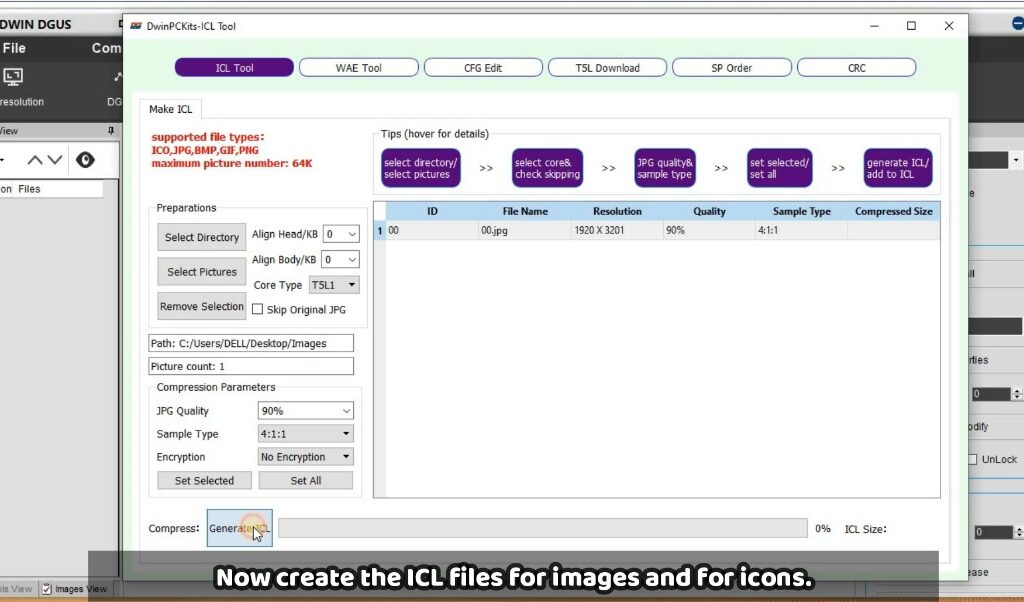
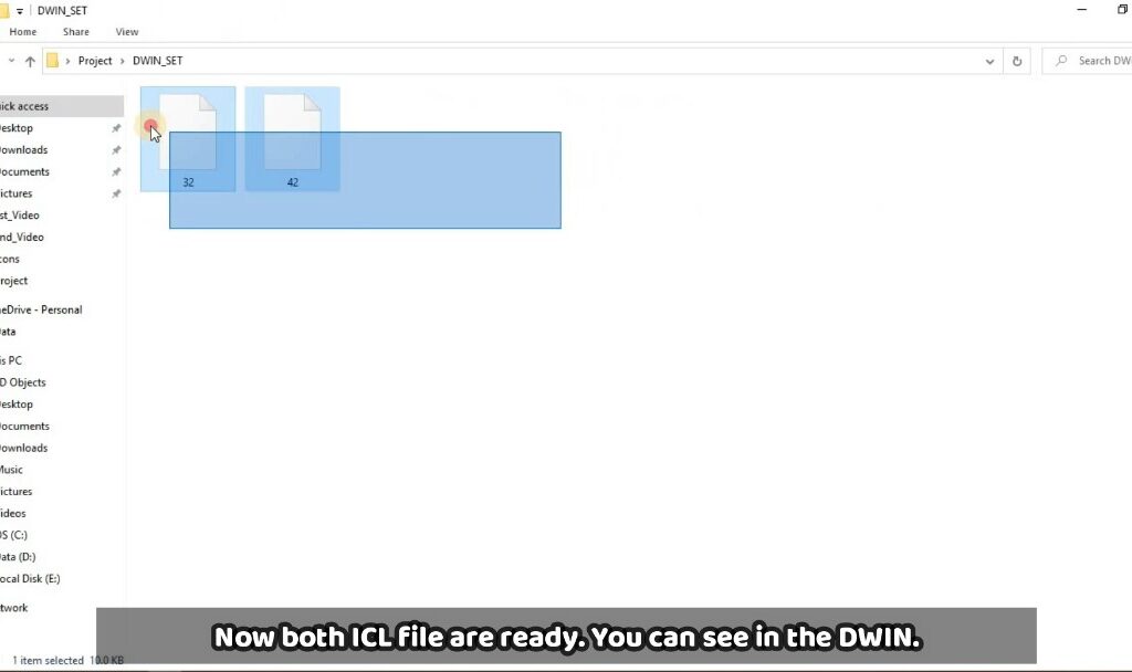
Step2 :- After converted images you have to make ICL file of every images and icons and then save these file in DWIN_SET folder with the name starting from 32..33…34……..64 and so on this is the rule, because memory is divided in different section so you have to name like this only, you can see ICL tool in below image through this you have to make ICL file.
Step 3 :- Now you need to add background image which we already converted into specific screen size, you can follow the below image.
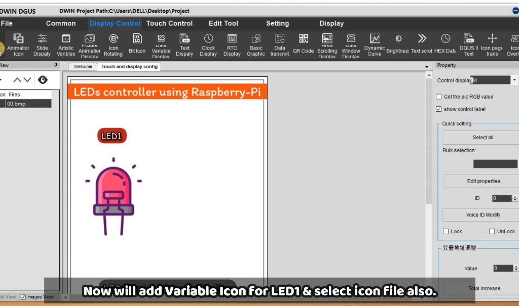
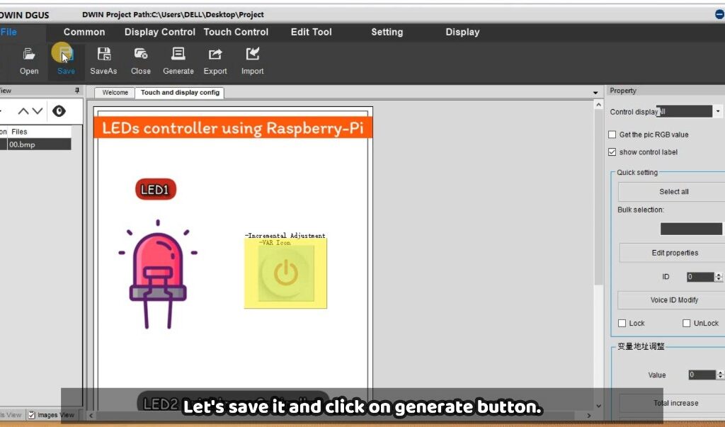
Now go in the display control and drag the “Var Icon” from there and add in the place of LED button as you can find in the below image. And also give the VP address and do other settings also.
Now add an action on that button for this you just need to add “Adjustment Increment” widget over that button icon and remember the VP address should be same as button has. And after that it will look like this as given in the below image.
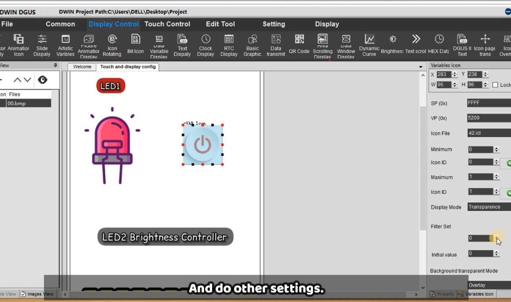
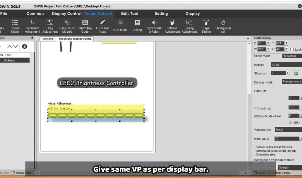
Now let’s add Brightness bar for LED-2 for this same go in Display control from there add “Slider Display” and then give the VP address and also select Icon of the bar. And then drag “Drag Adjustment” from Touch control and put it n that slider and give the VP address and do other setting also, you can follow the image.
By this we have completed the GUI design for this project and now we can go for Coding part so let’s move further.
For project file and Raspberry-Pi code you can check this link which is given below.
Raspberry-Pi connection and Code
Circuit-Diagram
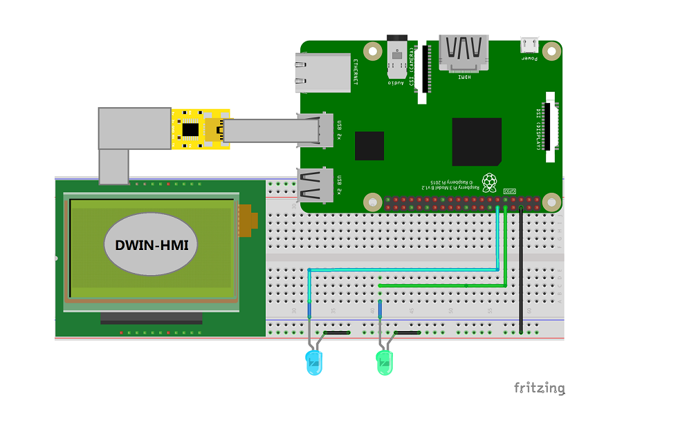
First you need to connect circuit like this with Raspberry-Pi as per given in the circuit. For communication between Raspberry-Pi I have used USB to TTL converter module that TTL module is connected with Tx & Rx of Display.
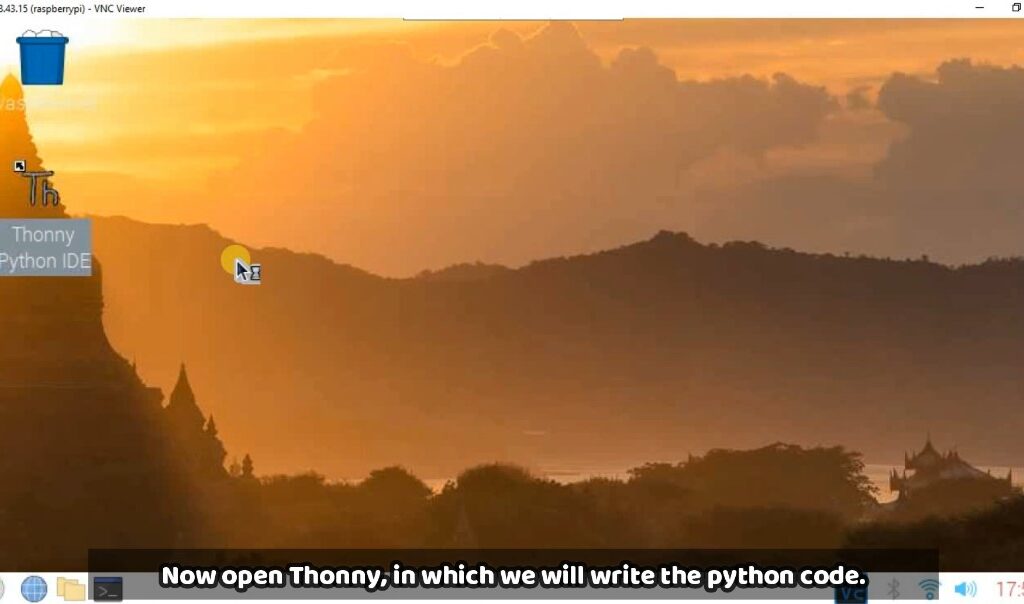
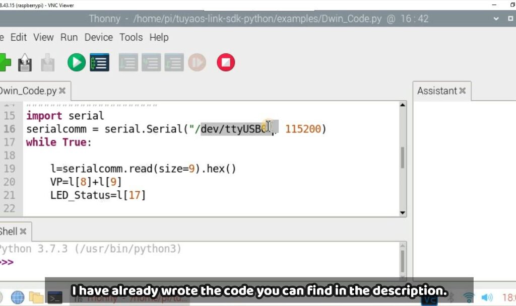
After connection you have to open you Raspberry-Pi, for that you can use VNC viewer and then open Thonny in that and then paste that code which I have created. If you want you can do changes according to your requirements.
Python Code :-
import RPi.GPIO as GPIO
GPIO.setmode(GPIO.BCM)
GPIO.setwarnings(False)
led1= 15
led2= 18
GPIO.setup(led1,GPIO.OUT)
GPIO.setup(led2,GPIO.OUT)
pwm = GPIO.PWM(led2,100)
pwm.start(0)
##########--------------------############
import serial
serialcomm = serial.Serial("/dev/ttyUSB0", 115200)
while True:

    l=serialcomm.read(size=9).hex()
    VP=l[8]+l[9]
    LED_Status=l[17]

    if(VP=='52'):
        if(LED_Status=='0'):
            print("LED1 ON")
            GPIO.output(led1,GPIO.HIGH)
        else:
            print("LED1 OFF")
            GPIO.output(led1,GPIO.LOW)

    elif(VP=='54'):
        #it will convert
        value=int(l[16]+l[17],16)
        pwm.ChangeDutyCycle(value)
        print(value)
To Run the code you need to click on Run button of Thonny IDE as given below and you will also get the on time value.
Note :- And this is the frame which I am receiving from HMI-Display at the time of pressing the any button.
Frame[8]={0x5a, 0xa5, 0x05, 0x82, sensor_H, sensor_L, 0x00, 0x00 } this is the frame which display is sending for any command, and here sensor_L & sensor_H is the address for that particular widget.
Testing/Output
Here is the output video you can see it for reference and if you are facing any difficulties you can watch the YouTube video, link is given below please find that. Or if you have any doubt please ask in comment section, I will try to give answer as soon as possible. And for any product query reach to them Email Id :- rock@dwin.com.cn
For this product or more different product you can contact Dwin-HMI supplier or their Team, contact details are given for any query related with Product, please reach to them if you have any.
YouTube Video
