
Description
This is a series of project which I am going to make on the STM32 so if you want to learn STM32 using Embedded C programming so you can subscribe my YouTube channel also and I am going to make article for each STM project so please be with me in this journey, so now let’s start with this project.
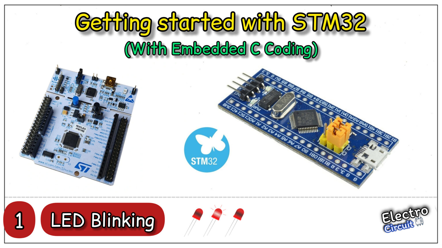
This project is first series of STM project series and basically all you know first basic project is LED blink project for every microcontroller, because here we learn basic things which we requires for proceed further. So that is why I selected this project. In this project I am blinking an led using STM32 microcontroller board. And this bord is STM32f103c8 you can get the information by click on this. And it look like this as mentioned below in the image.

As this board comes without debugger , so you have to purchase also debugger to download the code in the board if you are using this board so you can purchase both things from any online store.

But before proceeding further you have to download the STM32CubeIDE in which we are going to code and it will help you to upload the code in the microcontroller board.

Circuit Diagram
This is the circuit diagram which I have used in this project, In the circuit this LED is connected with GPIOA pin-number 5 as you can see in the circuit. You can directly connect LED because this STM32 board is working on 3.3v so if your board working on 5v then you have to use a resistor there with value of 220 to 1k ohm. So let’s move further in the coding part.

Embedded C code
#include <stdint.h>

#define RCC_BASE_ADD		  0x40021000U
#define GPIOA_BASE_ADD	    0x40010800U
#define OFFSET_APB2		   0x18U
#define OFFSET_CRL			0x00U
#define OFFSET_ODR			0x0CU


#define CLK_ENABLE_REG	     *(volatile uint32_t*)(RCC_BASE_ADD+OFFSET_APB2)
#define GPIOA_CRL			  *(volatile uint32_t*)(GPIOA_BASE_ADD+OFFSET_CRL)
#define GPIOA_ODR			  *(volatile uint32_t*)(GPIOA_BASE_ADD+OFFSET_ODR)


int main(void)
{
	 CLK_ENABLE_REG	|=(1<< 2);     //GPIOA clock enabled
	 GPIOA_CRL |=(3<<20);             //GPIOA configured as Output
	 GPIOA_CRL &=~(3<<22);

	 while(1)
	 {

		 GPIOA_ODR |=(1<<5);           //GPIOA PIN-5 HIGH
		 for(int i=0; i<100000;i++);
		 GPIOA_ODR &=~(1<<5);          //GPIOA PIN-5 LOW
		 for(int i=0; i<100000;i++);

	 }


	return 0;
}
To understand the code please see the YouTube vide for better understanding. Because in video I have wrote the whole code by using reference manual of the microcontroller. So whatever your microcontroller is you have to download the reference manual of it for coding purpose , so here is manual which I have used in this project.
Output Video
YouTube Video
