

Components List
• IC-555
• 220 Ohms & 10k Resistors
• 9Volt Battery and it’s clip
• Few Jumper Wires
• 10uF & 10nf(Ceramic) Capacitors
• 100k Variable Resistor
• Led
• Breadboard
Description
The 555 Timer IC can be connected either in its Monostable mode thereby producing a precision timer of a fixed time duration, or in its Bistable mode to produce a flip-flop type switching action. But we can also connect the 555 timer IC in an Astable mode to produce a very stable 555 Oscillator circuit for generating highly accurate free running waveforms whose output frequency can be adjusted by means of an externally connected RC tank circuit consisting of just two resistors and a capacitor.
The 555 Oscillator is another type of relaxation oscillator for generating stabilized square wave output waveforms of either a fixed frequency of up to 500kHz or of varying duty cycles from 50 to 100%. In the previous 555 Timer tutorial we saw that the Monostable circuit produces a single output one-shot pulse when triggered on its pin 2 trigger input.
Whereas the 555 monostable circuit stopped after a preset time waiting for the next trigger pulse to start over again, in order to get the 555 Oscillator to operate as an astable multivibrator it is necessary to continuously re-trigger the 555 IC after each and every timing cycle.
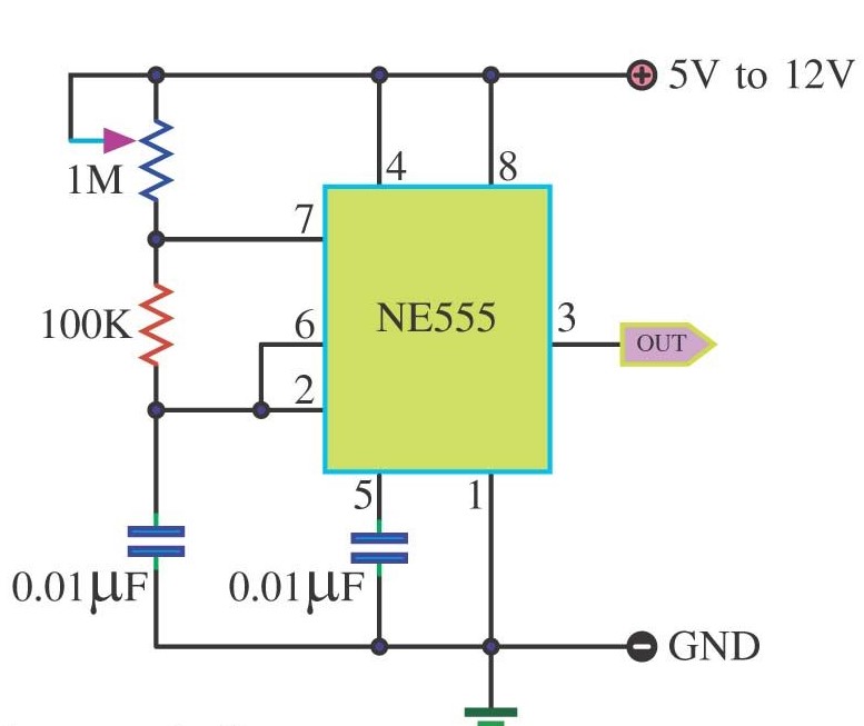
Circuit-Diagram
Working
PWM (Pulse Width Modulation) is a important feature of today’s every microcontroller due to its requirement for controlling many devices in every field of Electronics almost. PWM is widely used for motor controlling, lighting controlling etc. Sometime we do not use microcontroller in our applications and if we need to generate PWM without microcontroller then we prefer some general purpose ICs like op-amp, timers, pulse generators etc. Here we are using a 555 timer IC for generating PWM. 555 Timer IC is a very useful and general purpose IC which can be used in many applications.
The percentage of time in which the PWM signal remains HIGH (on time) is called as duty cycle. If the signal is always ON it is in 100% duty cycle and if it is always off it is 0% duty cycle.
Duty Cycle =Turn ON time/ (Turn ON time + Turn OFF time)

Frequency of a PWM :-
The frequency of a PWM signal determines how fast a PWM completes one period. One Period is complete ON and OFF of a PWM signal as shown in the above figure. In our tutorial we will set a frequency of 5KHz.
We can notice if LED being OFF for half second and LED being ON for other half second. But if Frequency of ON and OFF times increased from ‘1 per second’ to ’50 per second’. The human eye cannot capture this frequency. For a normal eye the LED will be seen, as glowing with half of the brightness. So with further reduction of ON time the LED appears much lighter.
YouTube Video
