List of Components
- Arduino UNO
- RGB LED/Strip
- Tuya Communication Board
- Few Jumper Wires
How RGB LED works?
An RGB LED is basically an LED package that can produce almost any color. RGB LEDs have three LEDs (Red, Green, and Blue) inside in it, with the help of these LEDs we can produce any color combination by changing the intensity of colors.
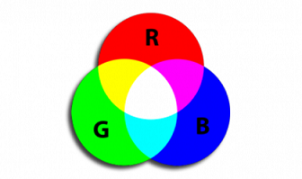
Let say we want Yellow color so for this we will required Red and Green color combination similarly for white color we will required Red ,Blue and Green color combination. And if we want different shades of that color just we have to change the intensity of these colors which is required for that.
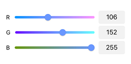
And as we are going to use Arduino UNO in this project which is a 8-Bit microcontroller , that’s mean we can get the (0-5) voltage value in the rage of 0-255 which will generate by with the help of PWM pins of Arduino
As you can see in below image ,here we have created three slide bar of Red ,Green and Blue LED with the range of 0-255 so this is the concept which we are going to use in this project so Let’s start.
GUI Designing and Implementation with Tuya
Firs will start from GUI and product implementation part for this will require account on Tuya IoT platform. Just click here you will redirect to the IoT platform of Tuya. After that register on this website and you will get interface like this.

click here for Tuya registration https://auth.tuya.com/?_source=293d65b4984ba4f9ba91ac4ef491a6ab
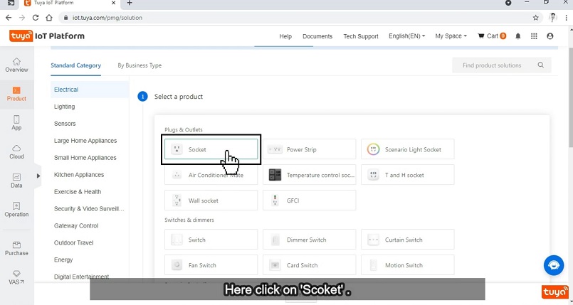
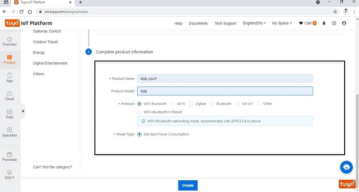
Now go for new product for that just click on the ‘Create’ button and select ‘Socket’ from that and this will provide a simple button function with this help will make a variable brightness controller bar which will control of intensity of LEDs.
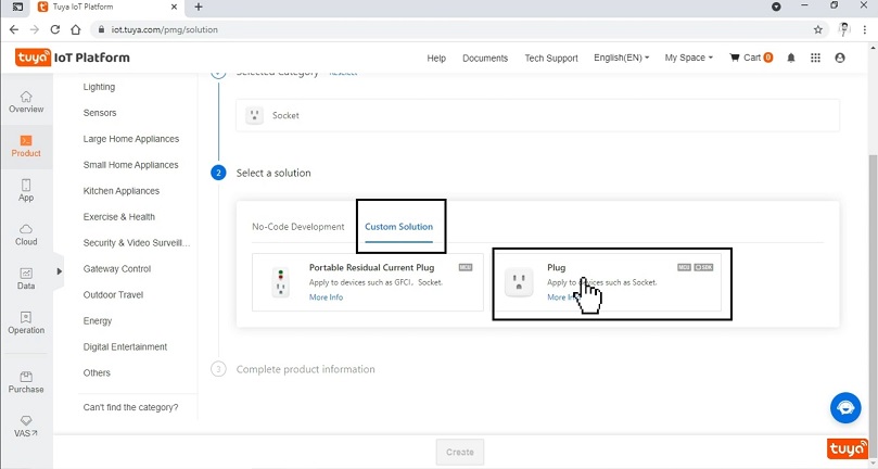
Now select custom function from here and then ‘Plug’ from this, after this will required some information about the product name and communication protocol fill these information and click on create button. After this part you have to fill all the information and after this you have to make a custom function to add the LEDs in this. follows these two images which are given below.
Now after clicking the create button let’s add the DPID there will be each ID for each color and these are the unique IDs which will transfer the data to the Arduino through Tuya cloud so keep remember their numbers for respective color.
Go to ‘Add’ button of custom function and then you will get this type of interface and here DP ID value will be already fill but if you want to change, then you can do after this there is DP name and identifier here we have given RED because this DPID is for Red LED and as we have discussed in working part we have given the value in the range of (0-255) ,and here pitch is 1 because we want value should be increase by one value and we have selected 0 as scale value. And after this you have to select data transfer type as you can see there are three options send ,report and send and report so we have selected send and report type of data transfer. Because this will give the return values of these LED’s state.
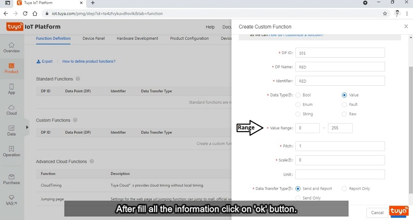
Now click on ok button after filled all the information. Similarly add all the DPIDs for Green and Blue LED and after this you will see this type of interface.

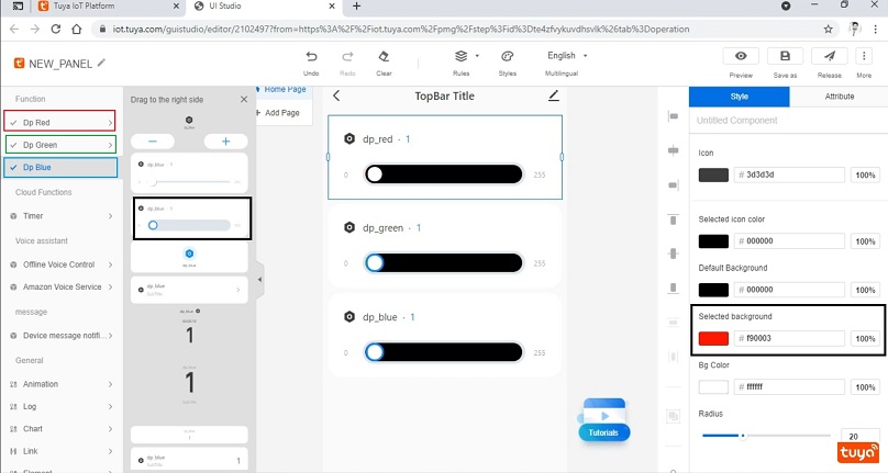
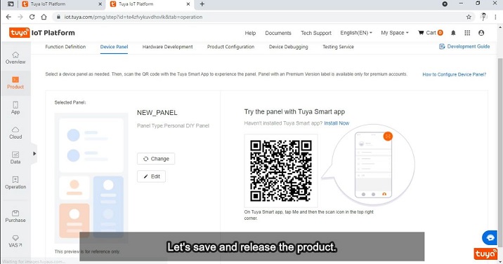
Now let’s design the GUI for RGB controller , for this go to device panel and here you will get a ‘Create blank panel’ option click on that and there are three pre defined function which are the Colors function . Now we will add all the colors function bar on this screen as you are seeing below. After this part select the background color for each bar according to their color.
After done all these things we will save this GUI by clicking save button and release it. If you want to test the designed GUI you will get this type of QR-code ,then open your ‘Tuya Smart’ mobile application and scan it you will get the designed GUI and if you want to do some changes you can do by click on edit button as you can see in below image.
Now we have done with GUI part if you have still any doubt please go through YouTube video just click here for video. Now let’s move further for Arduino coding.
Arduino Code
#include <TuyaWifi.h>
#include <SoftwareSerial.h>

TuyaWifi my_device;
SoftwareSerial DebugSerial(8,9);
int wifi_key_pin = 7;
unsigned char led_state = 0;


int red = 6;
int green = 5;
int blue = 3;


/* Data point define */
#define DPID_VALUE1  101
#define DPID_VALUE2  102
#define DPID_VALUE3  103
long dp_1 = 0;
long dp_2 = 0;
long dp_3 = 0;

unsigned char dp_array[][2] =
{
    {DPID_VALUE1, DP_TYPE_VALUE},
    {DPID_VALUE2, DP_TYPE_VALUE},
    {DPID_VALUE3, DP_TYPE_VALUE},
};

unsigned char pid[] = {"wxiufodios50ktaf"};
unsigned char mcu_ver[] = {"1.0.0"};

/* last time */
unsigned long last_time = 0;

void setup()
{
    Serial.begin(9600);
    DebugSerial.begin(9600);

    //Initialize led port, turn off led.
    pinMode(LED_BUILTIN, OUTPUT);
    digitalWrite(LED_BUILTIN, LOW);

    pinMode(red, OUTPUT);
    digitalWrite(red, LOW);
    pinMode(green, OUTPUT);
    digitalWrite(green, LOW);
    pinMode(blue, OUTPUT);
    digitalWrite(blue, LOW);

    //Initialize networking keys.
    pinMode(wifi_key_pin, INPUT_PULLUP);

    //Enter the PID and MCU software version
    my_device.init(pid, mcu_ver);
    //incoming all DPs and their types array, DP numbers
    my_device.set_dp_cmd_total(dp_array, 3);
    //register DP download processing callback function
    my_device.dp_process_func_register(dp_process);
    //register upload all DP callback function
    my_device.dp_update_all_func_register(dp_update_all);

    last_time = millis();
}

void loop()
{
    my_device.uart_service();

    //Enter the connection network mode when Pin7 is pressed.
    if (digitalRead(wifi_key_pin) == LOW) {
        delay(80);
        if (digitalRead(wifi_key_pin) == LOW) {
            my_device.mcu_set_wifi_mode(SMART_CONFIG);
        }
    }

    /* LED blinks when network is being connected */
    if ((my_device.mcu_get_wifi_work_state() != WIFI_LOW_POWER) && (my_device.mcu_get_wifi_work_state() != WIFI_CONN_CLOUD) && (my_device.mcu_get_wifi_work_state() != WIFI_SATE_UNKNOW)) {
        if (millis() - last_time >= 500) {
            last_time = millis();
            /* Toggle current LED status */
            if (led_state == LOW) {
                led_state = HIGH;
            } else {
                led_state = LOW;
            }

            digitalWrite(LED_BUILTIN, led_state);
        }
    }

    delay(10);
}

unsigned char dp_process(unsigned char dpid, const unsigned char value[], unsigned short length)
{
    switch (dpid)
    {

        case DPID_VALUE1:
            DebugSerial.println("Value type:");
            dp_1 = my_device.mcu_get_dp_download_data(DPID_VALUE1, value, length);
            DebugSerial.println();
            analogWrite(red,dp_1);
            my_device.mcu_dp_update(DPID_VALUE1, dp_1, 1);
        break;

        case DPID_VALUE2:
            DebugSerial.println("Value type:");
            dp_2 = my_device.mcu_get_dp_download_data(DPID_VALUE2, value, length);
            DebugSerial.println();
            analogWrite(green,dp_2);
            /* After processing the download DP command, the current status should be reported. */
            my_device.mcu_dp_update(DPID_VALUE2, dp_2, 1);
        break;


         case DPID_VALUE3:
            DebugSerial.println("Value type:");
            dp_3 = my_device.mcu_get_dp_download_data(DPID_VALUE3, value, length);
            DebugSerial.println();
            analogWrite(blue,dp_3);
            /* After processing the download DP command, the current status should be reported. */
            my_device.mcu_dp_update(DPID_VALUE3, dp_3, 1);
        break;

        default:
            break;
    }

    return SUCCESS;
}

void dp_update_all(void)
{
  my_device.mcu_dp_update(DPID_VALUE1, dp_1, 1);
  my_device.mcu_dp_update(DPID_VALUE2, dp_2, 1);
  my_device.mcu_dp_update(DPID_VALUE3, dp_3, 1);
}
Above given code is for Arduino as you can see we have divided this code into three parts first is void setup function in this part all initialization is done for LEDs and serial and its baud rate, and there are also function calling which because in Arduino every function call is done in the setup function. After this function there is void loop function which is using to connect with Wi-Fi because it will continuously run again and again and for the Wi-Fi triggering we are using pin number-7 of Arduino. this pin is required for the first time when we will add any new device/product with Tuya Smart app. For initialization this pin-7 should be connect with ground pin for up to 5 sec after after this remove that wire and then a new device will be pop-up in Tuya application for this you have to jus refresh it.
Then there is important function which is a switch case function and this function is using for to control each LED brightness separately with providing key case as a DPID value so when it will get any DPID information it will process it with adjusting the voltage value of that pin which is connected with respective LED color. For controlling thr Voltage through the value of DPID we are using analogWrite (pin-number , DPID-value); this function and this is the inbuilt function of Arduino.
Then there is call function which we run at every value when user sent the some information and it will update the current value of that DPID or we can say that voltage value at that time.
Now let’s move towards to get the output , for this we have to run this above code but before copy we have to do one change, whatever product you have created for this project , so each project has a product ID so copy yor product ID and paste it in the variable which in the initialization part
Put here your product ID
unsigned char pid[] = {“wxiufodios50ktaf”};
Now after this upload the code in the Arduino and after uploaded you have to connect Tuya communication board. and open you Tuya application and for Wi-Fi initialization connect pin-7 to ground for 5 sec and remove it and refresh your application.
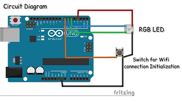
This is the circuit diagram in this manner our RGB LED is connected. and upper of Arduino Tuya communication board is connected.
Output Video.
As you can see in the output video we have three RGB bar are by changing these we are able to adjust any color.
And thankyou so much to read the article till now there is YouTube video on this project so please go through that video to understand the whole procedure in a better manner there is link for video go and check it out.
YouTube video