
Description
DWIN specialized in making High quality and cost effective HMI touch screens display.
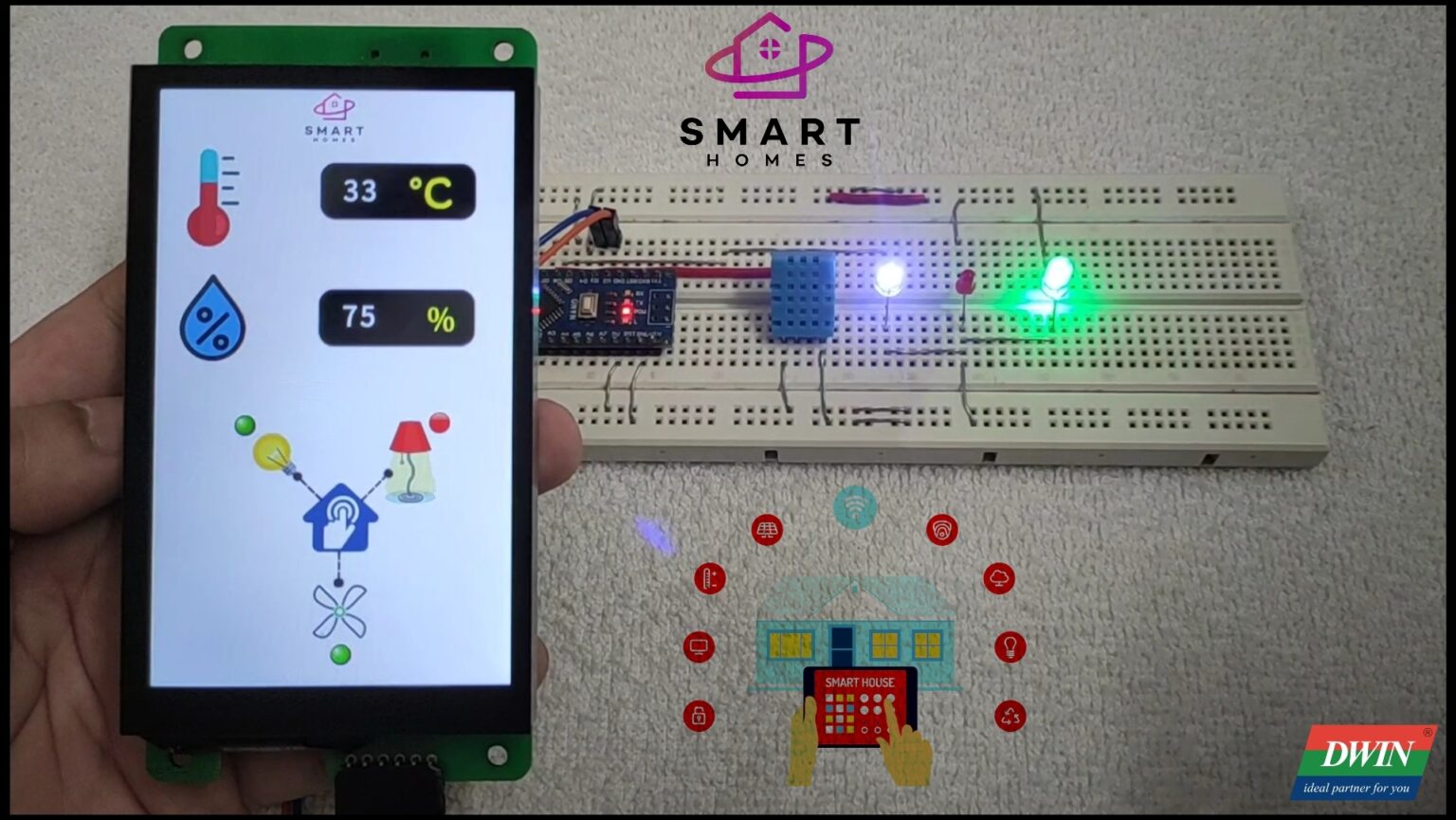
In this tutorial, I am going to make a Smart-Home controller with the help of this HMI. Here I have used just LEDs for output purpose, but if you want to implement for your Home you can use Relay to control the real light, Bulb & Fan of your Home. So let’s start with it and stay tune here to get the solution for Dwin-HMI display.
This DMG80480C043_02WTC has resolution of 480X800 and can be easily used with 5V compatible controller boards like Arduino Uno, Arduino Nano, Arduino Mega, PIC microcontrollers, 8051 family of microcontrollers, etc.
For this product or more different product you can contact Dwin supplier or their Team, contact details are given for any query related with Product, please reach to them if you have any.
Tool Installation
For tool installation, I already explained in the first tutorial of Dwin you can check this by clicking on given link. And this is require to proceed further so please check it, how to install the tools, then you can proceed further in this project to design GUI as you saw in the output video/YouTube so go through first Tutorial which is given below.
GUI Designing
Step1 :- First you have to make a new folder then go in GUI tool and click on new project and give the path of this project. Then convert that image which we are going to use for GUI, with the help of inbuilt tool “Picture conversion” . At the time of converting images give the path of Project folder.
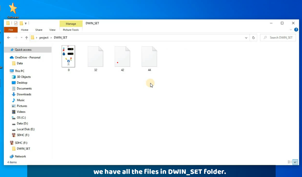
Step2 :- After converted images you have to make ICL file of every images and icons and then save these file in DWIN_SET folder with the name starting from 32..33…34……..64 and so on this is the rule, because memory is divided in different section so you have to name like this only, you can see ICL tool in below image through this you have to make ICL file.
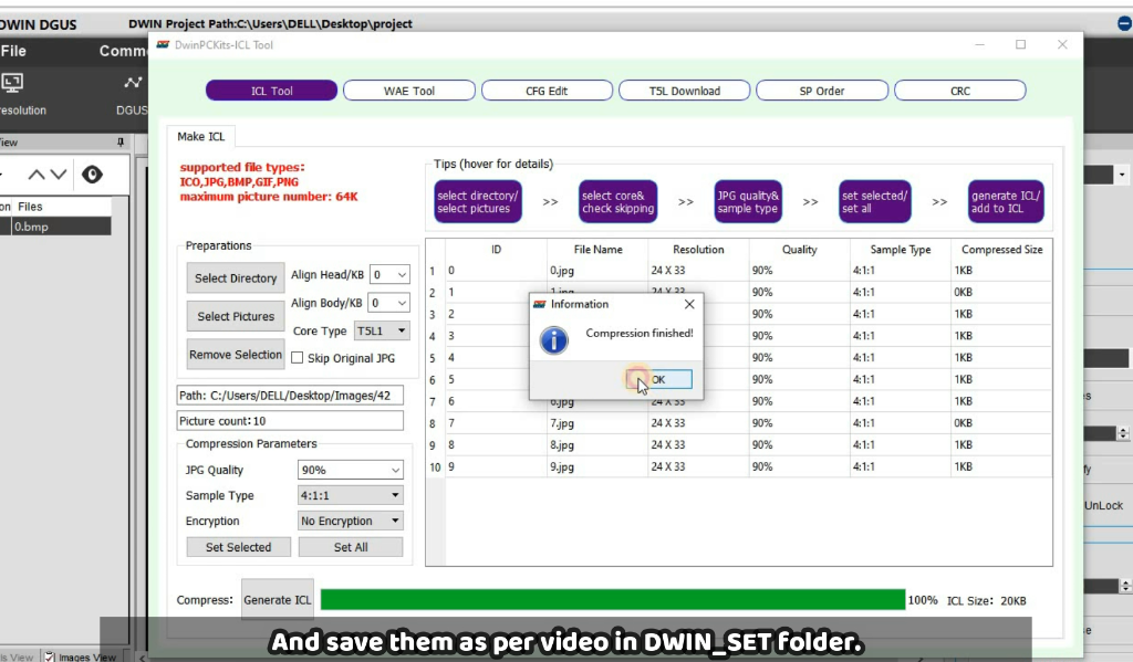
As, in this we have icons & image so, I have made two ICL file and these file are saved in the DWIN_SET folder as you can see in below image.
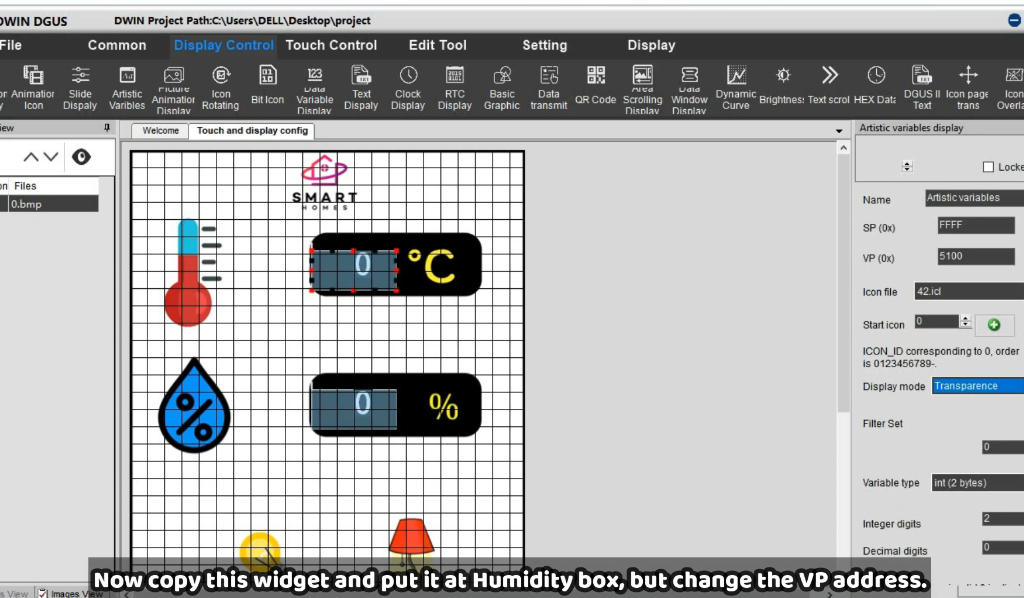
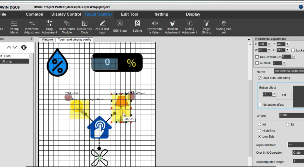
Step3:- We have two data box and three switches on screen as you saw in the output video. So for this first add Artistic variable widget in the place of temperature’s box and put VP address, I have put VP as 5100 for temperature and this Artistic variable require Icon file for the digit, and I already made that file as 42. So add that file in icon file and set initial value as zero and set integer digit as 2. Similarly do for Humidity box add same Artistic widget there only you need to change VP address.
Now go on buttons section here we need two widget one in variable icon and another one is Increment adjustment add both first for Light button and put VP address for both and it should be same for both widget, then set increment as ++ and step length by 1 and put it in cycle. you can find these setting in below image.
Now do same for all other two buttons and then save the project and then click on generate button.
Step4:– Now upload this project in display for this go in DGUS tool and add all the which are inside in the DWIN_SET folder. An connect your display with USB board after that click on Download button and it will take some time after this you are ready to connect your circuit with it. So now go further to complete it.
Circuit & Arduino code
Circuit-Diagram
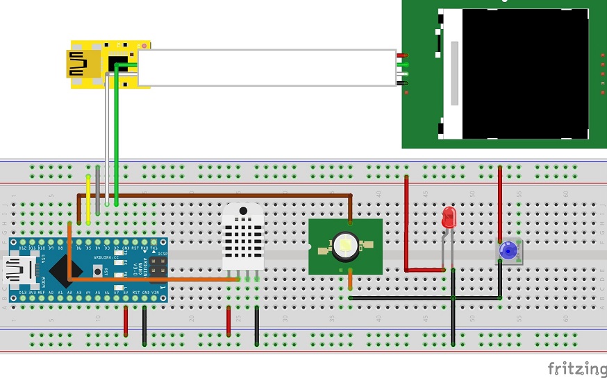
After done with GUI design you have to connect Display with other components as given in below circuit. As in this we are sending as well as receiving data. For sending purpose I am sending a frame with address of that sensor and value , and that value is updating on time similarly for receiving I am checking the serial receive frame for particular button with their addresses using switch case as you can see in the below code.
/* For Software serial */
#include <SoftwareSerial.h>
const byte rxPin = 2;
const byte txPin = 3;
SoftwareSerial mySerial (rxPin, txPin);
/* For temperature sensor */
#include "DHT.h"
#define DHTPIN 7
#define DHTTYPE DHT11
DHT dht(DHTPIN, DHTTYPE);
/* appliances pins */
int lamp = 4;
int fan = 5;
int light = 6;
/* Adresses of all sensors */
unsigned char Buffer[9];
#define temperature_add   0x51
#define humidity_add     0x52
unsigned char   Temperature[8] = {0x5a, 0xa5, 0x05, 0x82, temperature_add , 0x00, 0x00, 0x00};
unsigned char      Humidity[8] = {0x5a, 0xa5, 0x05, 0x82, humidity_add, 0x00, 0x00, 0x00};

void setup()
{
  mySerial.begin(115200);
  dht.begin();
  pinMode(lamp, OUTPUT);
  digitalWrite(lamp, LOW);
  pinMode(fan, OUTPUT);
  digitalWrite(fan, LOW);
  pinMode(light, OUTPUT);
  digitalWrite(light, LOW);
}
void loop()
{
  Data_Arduino_to_Display();
  delay(10);
  Data_Display_to_Arduino();
  delay(80);
}

void Data_Display_to_Arduino()
{
  if (mySerial.available())
  {
    for (int i = 0; i <= 8; i++) //this loop will store whole frame in buffer array.
    {
      Buffer[i] = mySerial.read();
    }

    if (Buffer[0] == 0X5A)
    {
      switch (Buffer[4])
      {
        case 0x53:   //for lamp
          if (Buffer[8] == 1)
          {
            digitalWrite(lamp, HIGH);
          }
          else
          {
            digitalWrite(lamp, LOW);
          }
          break;

        case 0x54:   //for fan
          if (Buffer[8] == 1)
          {
            digitalWrite(fan, HIGH);
          }
          else
          {
            digitalWrite(fan, LOW);
          }
          break;

        case 0x55:   //for light
          if (Buffer[8] == 1)
          {
            digitalWrite(light, HIGH);
          }
          else
          {
            digitalWrite(light, LOW);
          }
          break;

        default:
          break;
      }
    }
  }
}

void Data_Arduino_to_Display()
{
  int t = dht.readTemperature();
  int h = dht.readHumidity();
  Temperature[6] = highByte(t);
  Temperature[7] = lowByte(t);
  mySerial.write(Temperature, 8);
  Humidity[6] = highByte(h);
  Humidity[7] = lowByte(h);
  mySerial.write(Humidity, 8);
}
This is the syntax of fram which I am sendig to the HMI-Display to display the sensor data.
Frame[8]={0x5a, 0xa5, 0x05, 0x82, sensor_H, sensor_L, sensor_value_H, sensor_value_L } this is the frame which display is receiving from Arduino, and here sensor_L & sensor_H is the address for that particular sessor & sensor_value_H & sensor_value_L is the sensor value in High byte and Low byte respectively.
And this is the frame which I am receiving from HMI-Display at the time of pressig the any button.
Frame[8]={0x5a, 0xa5, 0x05, 0x82, sensor_H, sensor_L, 0x00, 0x00 } this is the frame which display is sending for any command, and here sensor_L & sensor_H is the address for that particular widget.
Testing/Output
Here is the output video you can see it for reference and if you are facing any difficulties you can watch the YouTube video, link is given below please find that. Or if you have any doubt please ask in comment section, I will try to give answer as soon as possible. And for any product query reach to them Email Id :- rock@dwin.com.cn
YouTube Video
