

List of Components
- Arduino
- NodeMCU
- Breadboard
- Few Jumper Wires & LEDs
- USB connector for Arduino and NodeMCU
What is Tuya?
Tuya Smart is a leading global IoT Cloud Platform that connects the intelligent needs of brands, OEMs, developers, and retail chains. The platform provides developers a one-stop IoT PaaS-level solution that contains hardware development tools, global cloud services, and smart business platform development, Tuya offering comprehensive ecosystem empowerment from technology to marketing channels to build the world’s leading IoT Cloud Platform.
Why Tuya IoT Platform?
If you want to make any IoT device or product there are certain problem or I can say complexity you will face at the time of making , but Tuya is design for to cut out all these extra steps and it do all process in backend automatically, you do not need to worry about communication protocol , controller, creating a server and all these things. Tuya is best because it provide all these things in its IoT platform. To get the experience of IoT Platform click here and then register it.
Creation of new product and GUI Designing.
Let’s start first with interface design, for this first go to this Tuya IoT platform link Click Here. https://auth.tuya.com/?_source=293d65b4984ba4f9ba91ac4ef491a6ab
Note:- If you do not have account on this platform use sign-up button to create new one, then go further.

After login you will get this type of interface which is an IoT platform to develop and make new projects.

Now click on Create button to make a new project and select these options as shown in the below image, that is first select ‘Socket’ then from that select ‘custom function’ and in that click on ‘Plug’ option and after clicked you will get a new page where you have to fill information about new project like which type of communication you are using in this and name of the project.

Now fill all the information as per given image below like name and protocol, after this click on create button.

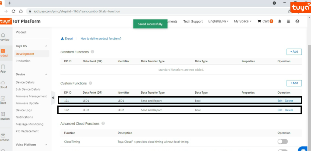
After this you will get this screen here select ‘Custom Function’ and from that click on ‘Add’ button to add the DPID for LED-1 and LED-2 ,as we are required to do ON and Off LEDs so here we have selected data type as Boolean because it has two state True and False.

As you can see in the image there we have added two DPIDs and these DPIDs has some parameter and here we have selected data transfer type as send and report because we are sending ON/Off command to the NodeMCU and NodeMCU will send back the state of LEDs.
After done with above part let’s build the interface for the Tuya application, and this editor look like this as you can see in the below image. For this you have to click on ‘Device Panel’ part after done with above part and then click on ‘Blank panel’ then you will redirect to this page with new tab.
There are many option to create a interface according to your choice only you have to drag that feature whatever you want to add in this area where ‘Drag Component’ is written. Now here Drag a LED-1 function to put it on mobile area region as given in the below image and similarly do for this thing for LED-2 also, and after this you will have two buttons as given in below image.
After done with this you have completed with designing part now it is time to save it ,for this click on save and then click on Release button. In process of this it will ask to test the design ,if you want to test you can test it for this you have to install ‘Smart Tuya’ application in your mobile and then click on ‘Add Device’ in you application and scan it with QR code which you will get on your screen. Now let’s move further to get the token ID.

Get the Token ID.
Why we required Token ID?
To burn the activation code in NodeMCU we require token ID and how to get this Token ID? for this you have to send an email to “devops@tuya.com” . And there are certain format to send this mail. As you can see in below image ,Subject should be in this format as given below.
Subject :- PID – your email ID
And after this type your Product ID and this Product ID you will get on which you have design ,so copy product ID from there and paste it on body area of email and do not type anything extra, as you can see in the image is should be in this format only.

After sent it , you will get reply from their side and in reply they will send you Token ID only, as you can see in above image. Now let’s move further to get activated this token ID for this we will use Tuya PMS platform.
Registration & activation on PMS Tuya platform.
Now click here to get this website or you can simply search for that on Google as Tuya PMS.

Now create an account on this platform and remember these credential for further procedure. After this click on login button and and click on ‘Work Order’ and in that click on ‘Activation code’ to activate the token ID . Now put here your token ID which you got from email and then click on ‘Confirm’ button. To check that token is activated or not ? go to ‘Activation Code list’ and if are able to see activated token id there ,that means you have completed with this part. So now go for the burning firmware in NodeMCU.

Installing TYDA & Driver.
Here is the link for this software and driver Click Here. Download it and this is in ‘zip’ file ,after downloaded you have to extract it and you will get two things as shown in the below image. First we will install the driver.

Now open that above Driver file and you will get these options as given below select that driver which is highlighted in the below image , and this driver is for 64-bit Computer and if you have 32-bit computer then install below one driver.

Now install the TYDA software and open it. The login credential will be same as PMS login details , so now login in this software and it may be in Chinese language by default to change it follow below image.


Now burn the code in Arduino but before this we have to set some parameters , to set parameter go to setup and this screen will popup and select these values as given in below image.

After setting up these things now connect NodeMCU with your computer and to check it is connected or not ? for this go to Device Manager and it should be look like this as in below image and with tis note down that COM number because we will require in further steps .

Now click om ‘Enter Token’ button and a screen will come like this and here you have to paste your Token ID here and also click on Firmware download checkbox, after that select COM as you can see in my case it is COM8, so I have selected that COM Now click on RUN button to burn the activation code.

After uploaded you will get this message on your screen as shown in above image. So great ! we have successfully completed this part also. Now let’s go for the circuit connection.
Connection & Upload code in Arduino.
After done with above part now let’s connect NodeMCU and Arduino together and with this also Connect two LEDs as per the circuit diagram. Here I am using two LEDs and if you want t0 add more LEDs you can add it but according to that you have to change your design and Arduino code.

Arduino Code :-
#include <TuyaWifi.h>
#include <SoftwareSerial.h>
TuyaWifi my_device;
/* Current LED status */
unsigned char led_state = 0;
unsigned char led_state1 = 0;
unsigned char led_state2 = 0;
/* Connect network button pin */
int key_pin = 7;
int led1=2;
int led2=3;
/* Data point define */
#define DPID_SWITCH1 101
#define DPID_SWITCH2 102
unsigned char dp_array[][2] =
{
  {DPID_SWITCH1, DP_TYPE_BOOL},
  {DPID_SWITCH2, DP_TYPE_BOOL},
};
unsigned char pid[] = {"160z1sanoqsribbr"};
unsigned char mcu_ver[] = {"3.1.4"};
/* last time */
unsigned long last_time = 0;
void setup()
{
  // Serial.begin(9600);
  Serial.begin(9600);
  //Initialize led port, turn off led.
  pinMode(LED_BUILTIN, OUTPUT);
  digitalWrite(LED_BUILTIN, LOW);
  pinMode(led1, OUTPUT);
  digitalWrite(led1, LOW);
  pinMode(led2, OUTPUT);
  digitalWrite(led2, LOW);
  //Initialize networking keys.
  pinMode(key_pin, INPUT_PULLUP);
  //Enter the PID and MCU software version
  my_device.init(pid, mcu_ver);
  //incoming all DPs and their types array, DP numbers
  my_device.set_dp_cmd_total(dp_array, 2);
  //register DP download processing callback function
  my_device.dp_process_func_register(dp_process);
  //register upload all DP callback function
  my_device.dp_update_all_func_register(dp_update_all);
  last_time = millis();
}
void loop()
{
  my_device.uart_service();

  //Enter the connection network mode when Pin7 is pressed.
  if (digitalRead(key_pin) == LOW) {
    delay(80);
    if (digitalRead(key_pin) == LOW) {
      my_device.mcu_set_wifi_mode(SMART_CONFIG);
    }
  }
  /* LED blinks when network is being connected */
  if ((my_device.mcu_get_wifi_work_state() != WIFI_LOW_POWER) && (my_device.mcu_get_wifi_work_state() != WIFI_CONN_CLOUD) && (my_device.mcu_get_wifi_work_state() != WIFI_SATE_UNKNOW)) {
    if (millis()- last_time >= 500) {
      last_time = millis();

      if (led_state == LOW) {
        led_state = HIGH;
      } else {
        led_state = LOW;
      }
      digitalWrite(LED_BUILTIN, led_state);
    }
  }
  delay(10);
}
unsigned char dp_process(unsigned char dpid,const unsigned char value[], unsigned short length)
{
  switch(dpid) {
    case DPID_SWITCH1:
      led_state1 = my_device.mcu_get_dp_download_data(dpid, value, length); /* Get the value of the down DP command */
      if (led_state1) {
        //Turn on
        digitalWrite(led1, HIGH);
      } else {
        //Turn off
        digitalWrite(led1, LOW);
      }
      //Status changes should be reported.
      my_device.mcu_dp_update(dpid, value, length);
    break;
    case DPID_SWITCH2:
      led_state2 = my_device.mcu_get_dp_download_data(dpid, value, length); /* Get the value of the down DP command */
      if (led_state2) {
        //Turn on
        digitalWrite(led2, HIGH);
      } else {
        //Turn off
        digitalWrite(led2, LOW);
      }
      //Status changes should be reported.
      my_device.mcu_dp_update(dpid, value, length);
    break;

    default:break;
  }
  return SUCCESS;
}

void dp_update_all(void)
{
  my_device.mcu_dp_update(DPID_SWITCH1, led_state1, 1);
  my_device.mcu_dp_update(DPID_SWITCH2, led_state2, 1);
}
Before uploading above Arduino code change the product ID[pid] and put your product ID there that section of code given below in which you have to do changes.
unsigned char pid[] = {"160z1sanoqsribbr"};
unsigned char mcu_ver[] = {"3.1.4"};
After done with changes now upload the code in your Arduino and at the time of uploading remove the (Tx & Rx) wire from NodeMCU other wise it will give the error and connect these wire when uploading will done.
Now connect pin-7 of Arduino with ground pin for up to 5 sec after after this remove that wire this thing require for to enter in pairing mode after done with this now open ‘Tuya Smart’ application in your mobile and follow these steps.
Setup for ‘Smart Tuya’ application.
After done with above part, now open ‘Tuya Smart’ application in your mobile and follow these steps.
[1] Click on ‘Add Device’ button
[2] Then select ‘Electrcal’ from that.
[3] From Electrical select Socket(Wi-Fi).
[4] Now enter Wi-Fi name and its password
[5] Click ok on next button.
[6] It will take some time and your device will add in you Smart Tuya application.
Output
This is the output video, as you can see in the video I am using two LEDs and I am able to On and Off these LEDs with the help of Smart Tuya mobile application.
Now we have completed with this project if you want to try other Tuya project just click here
YouTube Video
Thankyou so much to read the article till now there is YouTube video on this project so please go through that video to understand the whole procedure in a better manner there is link for video go and check it out.
