
Description
In electronics projects, creating an interface between user and system is very important. This interface could be created by displaying useful data, a menu, and ease of access. A beautiful design is also very important. There are several components to achieve this like TFT Displays. For more information Click Here.
Stone Technologies is a professional Manufacturer of HMI Intelligent TFT LCD modules. Depending on the application the Stone Technologies offers Industrial Type, Advanced type, and Civil Type Intelligent TFT LCD modules available in different sizes. Visit Here.
GUI Designing
The HMI intelligent TFT LCD Module is provided with all the necessary documents explaining the basic connection, Development Software, GUI individual Design, and operation. But for further description and knowledge please find the below explanation and ( Note :- the details of the products used in the project is given in the procedure).
The product manual gives you an overview of the Communication and Operation, Basic functions, working principle, GUI Design Software, Information about the Industrial type, Advanced Type, and Civil Type HMI TFT LCD Modules Below is the procedure that we have to follow to build this project.
Firstly for the design download the GUI software provided in the link given below. Then further proceeding step would be to click on “file->New” the same can be seen in the video itself. Now further select the screen size would be 800 X 480 for a 5 inch display. After both the steps have been completed then select and add the image and icon of GUI design for the display. The same can be found in the below article. Refer the below video to follow the step by step procedure for any difficulty in the procedure. Add a button so that you can switch from screen “1” to screen “2” and vice-versa PS- (Refer video for ambiguity in the procedure). The next step indicates adding and dragging the ‘Drag adjustment ()’ to fit the scale. Now select address 0086 as per the Arduino code. It can be selected from the right hand column as displayed in the video which is in the property settings. Now add slider scale and set address as 0086 (as per the code). After this follow these steps “Tool -> Icon Generation Tool -> Choose image path -> Generate icon”. (Note:- you can find all the image and procedure in this article). Now select the icon for the icon slider. From the property settings, in the display format add the integer values.
Furthermore select the unit in which you want the distance to be displayed. After all the steps have been followed properly save the file and click on configure file. After all the procedure is being completed copy the image into a storing device like pen drive and upload it STONE Hmi Display. Follow the for a detailed explanation on the GUI design. The video explains step by step and in simple and lucid manner.
► Size: 5″
► CPU: Cortex M4
► Resolution: 800×480 (16:9)
► Interface: RS232/RS485/TTL/USB
► Viewing Area (mm): 108.0*64.8
►Brightness(cd/m²): 400; 350; 400
Video For GUI Design (Step By Step)
The Product used in the project is a smart and vibrant TFT Display with a 5 inch display and resolution of 800 X 480. To buy and work on this exciting product Click Here.

Follow above procedure and video for complete GUI Design and below are the contents for the constructing the distance measurement.
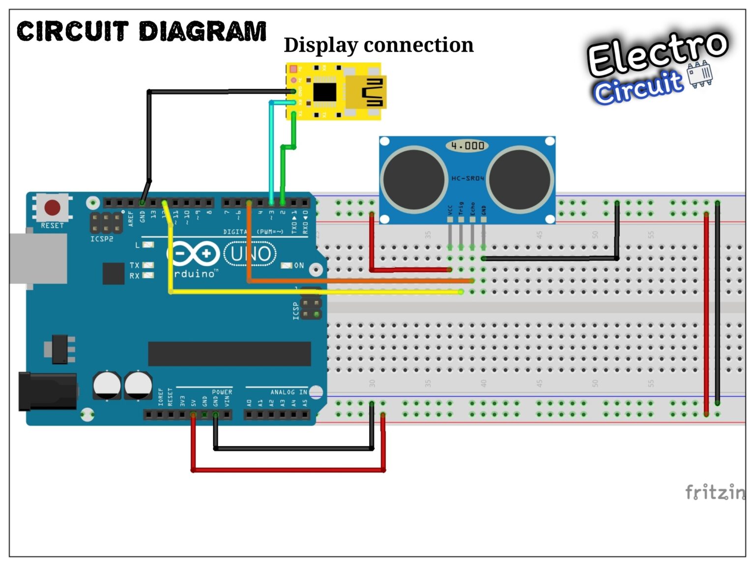
Circuit Diagram

Working

The working principle of this module is simple. It sends an ultrasonic pulse out at 40kHz which travels through the air and if there is an obstacle or object, it will bounce back to the sensor. By calculating the travel time and the speed of sound, the distance can be calculated.
Ultrasonic sensors are a great solution for the detection of clear objects. For liquid level measurement, applications that use infrared sensors, for instance, struggle with this particular use case because of target translucence. For presence detection, ultrasonic sensors detect objects regardless of the color, surface, or material (unless the material is very soft like wool, as it would absorb sound. To detect transparent and other items where optical technologies may fail, ultrasonic sensors are a reliable choice.
Pin Configuration.

As shown above the Ultrasonic sensor is a 4 pin module, whose pin names are Vcc, Trigger, Echo and Ground respectively. This sensor is a very popular sensor used in many applications where measuring distance or sensing objects are required. The module has two eyes like projects in the front which forms the Ultrasonic transmitter and Receiver. The sensor works with the simple high school formula that is
Distance = Speed × Time
The current consumed by the sensor is less than 15mA and hence can be directly powered by the on board 5V pins (If available). The Trigger and the Echo pins are both I/O pins and hence they can be connected to I/O pins of the microcontroller. To start the measurement, the trigger pin has to be made high for 10uS and then turned off. This action will trigger an ultrasonic wave at frequency of 40Hz from the transmitter and the receiver will wait for the wave to return. Once the wave is returned after it getting reflected by any object the Echo pin goes high for a particular amount of time which will be equal to the time taken for the wave to return back to the sensor.
Application:-
1.Used to avoid and detect obstacles with robots like biped robot, obstacle avoider robot, path finding robot etc.
2.Used to measure the distance within a wide range of 2cm to 400cm
3.Can be used to map the objects surrounding the sensor by rotating it
4.Depth of certain places like wells, pits etc can be measured since the waves can penetrate through water.
Connections :-
1.Connect VCC on the ultrasonic sensor to the 5V pin on the Arduino.
2.Connect the Trig pin on the ultrasonic sensor to pin 2 on the Arduino.
3.Connect the Echo pin on the ultrasonic sensor to pin 3 on the Arduino.
4.Connect the GND on the ultrasonic sensor to GND on the Arduino.
Note:- please see the circuit for further reference with respect to connections
Arduino Code
#include <SoftwareSerial.h>
SoftwareSerial screenserial(2, 3); // RX, TX

const int pingPin = 5; // Trigger
const int echoPin = 12;

#define ta 0x86
unsigned char ta_send[8]= {0xA5, 0x5A, 0x05, 0x82, 0x00, ta, 0x00, 0x00};
int x=0;
void setup()
{
  Serial.begin(115200);
  screenserial.begin(115200);
}

void loop()
{
   long duration, inches, cm;
   pinMode(pingPin, OUTPUT);
   digitalWrite(pingPin, LOW);
   delayMicroseconds(2);
   digitalWrite(pingPin, HIGH);
   delayMicroseconds(10);
   digitalWrite(pingPin, LOW);
   pinMode(echoPin, INPUT);
   duration = pulseIn(echoPin, HIGH);
   cm = microsecondsToCentimeters(duration);
   Serial.print("Distance : ");
   Serial.print(cm);
   Serial.print("cm");
   Serial.println("");

///////////////send data to display///////////
  ta_send[6]=cm/256;
  ta_send[7]=cm%256;
  screenserial.write(ta_send,8);
  delay(200);
}
long microsecondsToInches(long microseconds)
{
   return microseconds / 74 / 2;
}
long microsecondsToCentimeters(long microseconds)
{
   return microseconds / 29 / 2;
}
For more such interesting projects follow @electrocircuit and for details of product visit Stone Technologies by Clicking Here.