
Description
DWIN specialized in making High quality and cost effective HMI touch screens display.
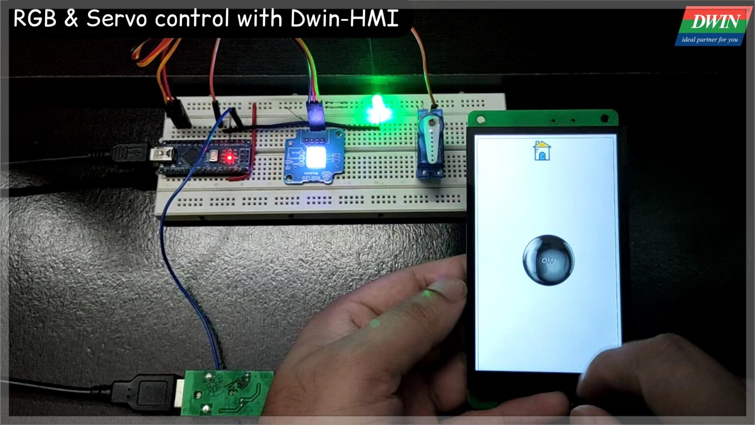
In this tutorial, I am going to make a controller for Servo-motor and a RGB controller with the help of this HMI. So by this we will learn & understand how to control any device/components through Dwin-display using Arduino, so let’s start with it and stay tune here to get the solution for Dwin-HMI display.
This DMG80480C043_02WTC has resolution of 480X800 and can be easily used with 5V compatible controller boards like Arduino Uno, Arduino Nano, Arduino Mega, PIC microcontrollers, 8051 family of microcontrollers, etc.
For this product or more different product you can contact Dwin supplier or their Team, contact details are given for any query related with Product, please reach to them if you have any.
You can use this coupon DWINROCK0760 to get discount & 𝐈𝐟 𝐲𝐨𝐮 𝐰𝐚𝐧𝐭 𝐭𝐨 𝐠𝐞𝐭 𝐟𝐫𝐞𝐞 𝐬𝐚𝐦𝐩𝐥𝐞𝐬 𝐲𝐨𝐮 𝐜𝐚𝐧 𝐜𝐨𝐧𝐭𝐚𝐜𝐭 𝐭𝐡𝐞𝐦.
Tool Installation
For tool installation, I already explained in the first tutorial of Dwin you can check this by clicking on given link. And this is require to proceed further so please check it, how to install the tools, then you can proceed further in this project to design GUI as you saw in the output video/YouTube so go through first Tutorial which is given below.
GUI Designing
For GUI there are few steps which you have to follow for proceeding further in a easy way.
Step1 :- First you have to make a new folder then go in GUI tool and click on new project and give the path of this project. Then convert that image which we are going to use for GUI, with the help of inbuilt tool “Picture conversion” . At the time of converting images give the path of Project folder.
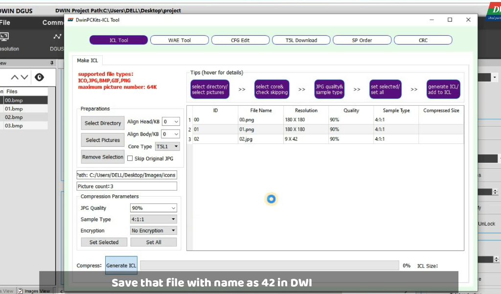
Step2 :- After converted images you have to make ICL file of every images and icons and then save these file in DWIN_SET folder with the name starting from 32..33…34……..64 and so on this is the rule, because memory is divided in different section so you have to name like this only, you can see ICL tool in below image through this you have to make ICL file.
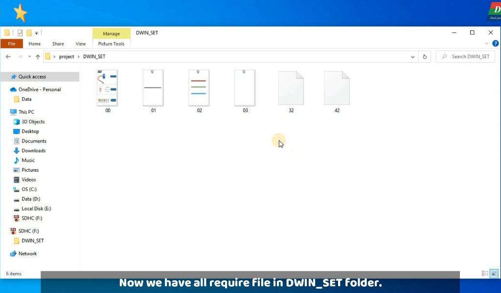
As, in this we have icons & image so, I have made two ICL file and these file are saved in the DWIN_SET folder as you can see in below image.
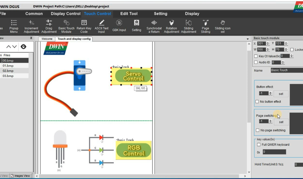
Step3 :- Now add ‘Basic Touch’ widget on image for the page switching , then select the respective page for that button. And do this thing for all the button which we have, you can see the below image for better understanding.
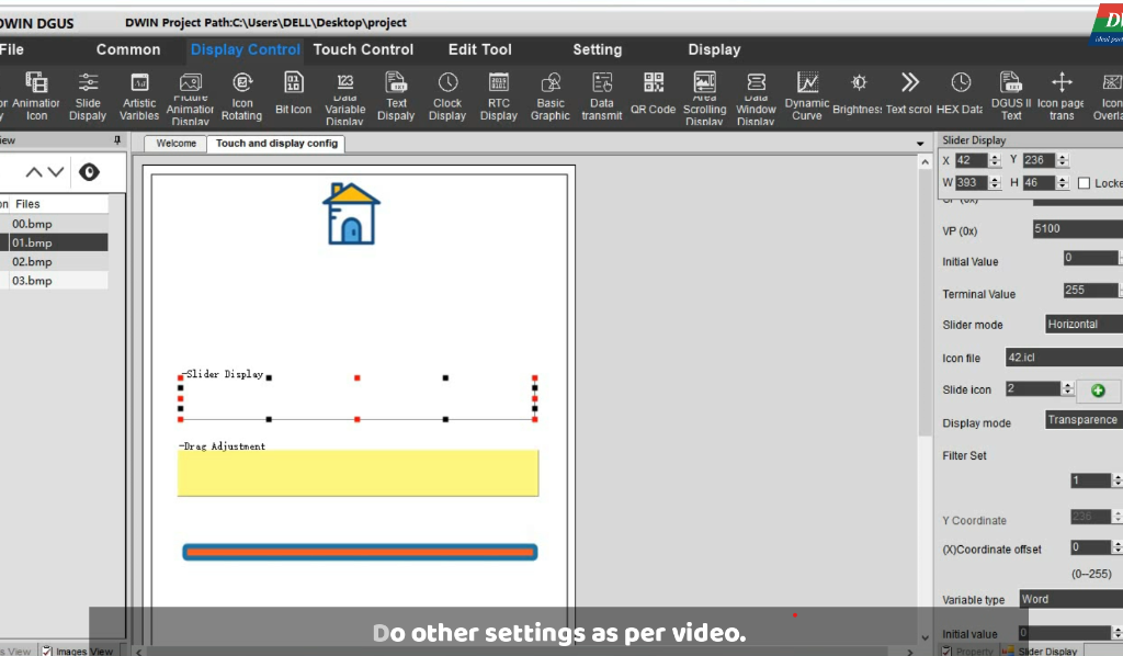
Now go on next screen add there Slider display & Drag adjustment widget to make a slider button for Servo motor as you can see in the image. And give a VP address as 5100, you can also give different address , and this address is important as we are going to get this slider value in code.
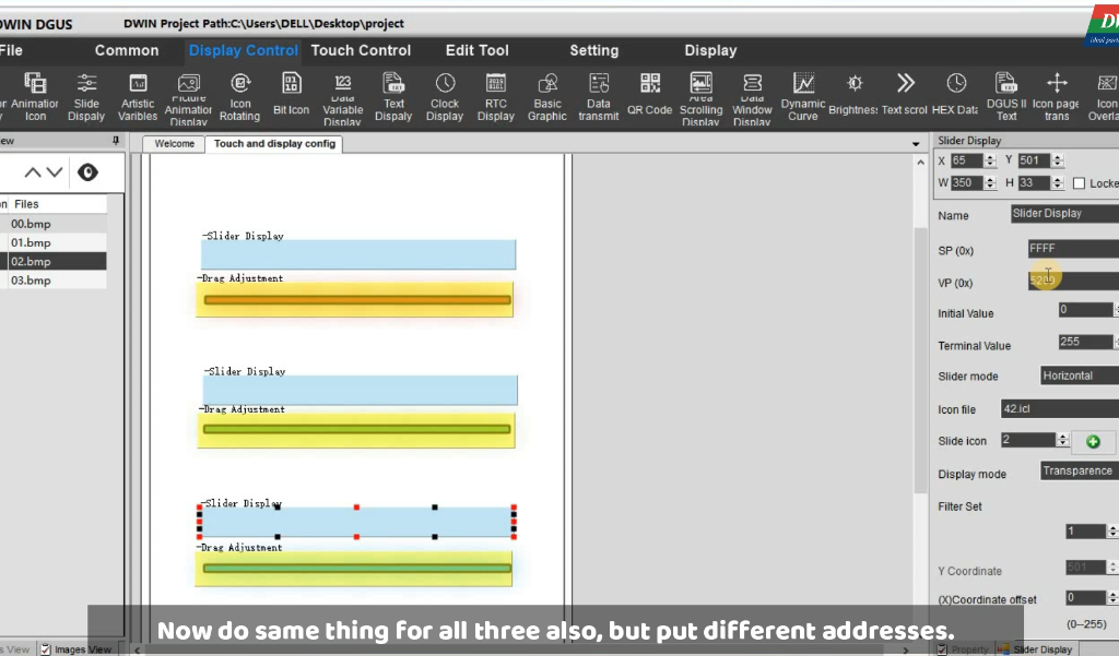
Now go on next screen at which we have three slider, so here do as we have done above but here do for each slider you and have to give different address of VP. you can find the modification in below image.
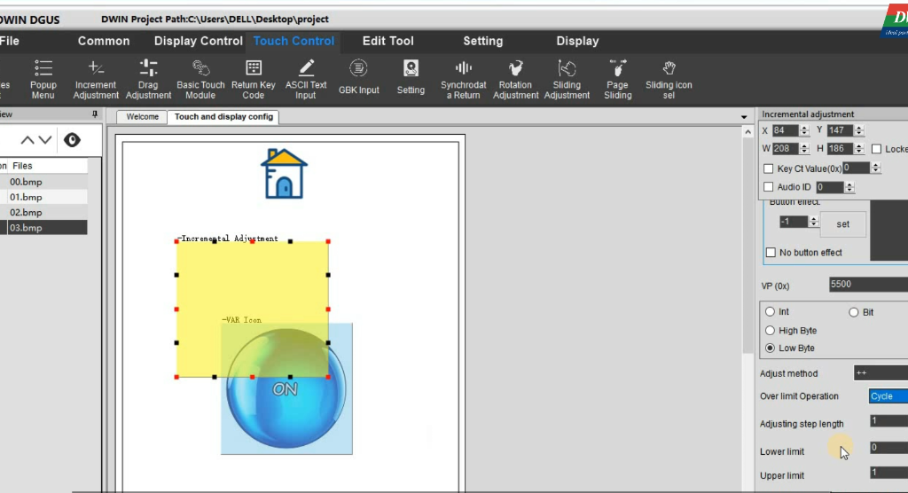
On next screen we need to add Icon for LED on/off purpose, for this you have to add two widget there also one for button and another for icon. In case of button add Increment Adjustment widget and put 5500 as VP address and do other settings as per image. Then for icon purpose select Variable Icon widget and then give the same VP address here also then select those initial and final image for button effect.
So now you are done with GUI design, and you can proceed toward circuit and coding part but before that save the project and then click on generate button.
Step4:– Now upload this project in display for this go in DGUS tool and add all the which are inside in the DWIN_SET folder. An connect your display with USB board after that click on Download button and it will take some time after this you are ready to connect your circuit with it. So now go further to complete it.
Circuit & Arduino code
After done with GUI design you have to connect Display with other components as given in below circuit. As here I have used servo, RGB and LED for this project so you can find all these components in the circuit. As all component require data from Display side, so here only display is sending the signal to the Arduino and this signal in the form of frame of HEX, here is the example of this frame which I have use in the code.
Circuit-Diagram
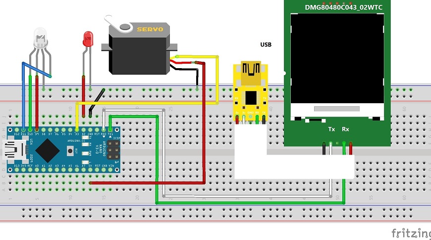
Frame[8]={0x5a, 0xa5, 0x05, 0x82, sensor_H, sensor_L, 0x00, 0x00 } this is the frame which display is sending for any command, and here sensor_L & sensor_H is the address for that particular widget.
Example :- If we have put the VP address for a button as 5100 so here sensor_H=0x51 and sensor_L will be 0x00. This is the concept which I have used in the code.
Arduino-Code
unsigned char Buffer[9];
int red=9;
int green =10;
int blue =11;
int servo =3;
int led=2;
void setup()
{
  Serial.begin(115200);

  pinMode(servo, OUTPUT);
  digitalWrite(servo,LOW);
  pinMode(red, OUTPUT);
  digitalWrite(red,LOW);
  pinMode(green, OUTPUT);
  digitalWrite(green,LOW);
  pinMode(blue, OUTPUT);
  digitalWrite(blue,LOW);
  pinMode(led, OUTPUT);
  digitalWrite(led,LOW);
}

void loop()
{
 if(Serial.available())
  {
    for(int i=0;i<=8;i++)   //this loop will store whole frame in buffer array.
    {
    Buffer[i]= Serial.read();
    }

    if(Buffer[0]==0X5A)
      {
        switch(Buffer[4])
        {
          case 0x51:   //for servo
            Serial.println(Buffer[8]);
            analogWrite(servo,Buffer[8]);
            break;

          case 0x52:   //for red
            Serial.println(Buffer[8]);
            analogWrite(red,Buffer[8]);
            break;

          case 0x53:   //for green
            Serial.println(Buffer[8]);
            analogWrite(green,Buffer[8]);
            break;


          case 0x54:   //for blue
            Serial.println(Buffer[8]);
            analogWrite(blue,Buffer[8]);
            break;

          case 0x55:  //for led
            if(Buffer[8]==1)
            { digitalWrite(led,HIGH);
              Serial.println("led on");}
            else
            {digitalWrite(led,LOW);
              Serial.println("led off");}
            break;


          default:
           Serial.println("Nothing");
           break;
        }
    }
  }
delay(10);
}
As you can see here in code, I have used the one for loop for receiving the and this for loop receiving that exact same frame of data as mentioned above so after that I am checking the particular address values by using swich case statements as you saw in the code. You can find the code section for each components, because I have commented all the things in the code itself.
Now I think you understood the circuit and code working also, so now upload the code in the Arduino board, here I have used the Arduino nano but if you want to use other you can use it, Before uploading don’t forget to select the port and board and at the time of uploading remove that Rx & TX pin after upload connect them.
Testing/Output
Here is the output video you can see it for reference and if you are facing any difficulties you can watch the YouTube video, link is given below please find that. Or if you have any doubt please ask in comment section, I will try to give answer as soon as possible. And for any product query reach to them Email Id :- rock@dwin.com.cn
YouTube-Video
